Intel® Server Board S2600CO Family TPS Functional Architecture Overview
Revision 1.0 31
Intel order number G42278-002
Intel® C600
Series Chipset
Intel®
Ethernet
Controller
I350
Dual 1Gb LAN
Intel® Xeon®
E5-2600
CPU 1
Intel® Xeon®
E5-2600
CPU2
Slot 2: x16 Conn
Slot 1 x8 Conn
Slot 3: x16 Conn
DMI2 PCIe Gen2 x4 (4GB/s)
QPI
QPI
P2 P1P3P0
IOU0 IOU2IOU1
P1P3 P2P0
IOU2
IOU1
IOU0
PCIe Gen
3
x
16
(32
GB
/s
)
PCIe Gen3 x16(32GB/s)
Slot 5: x16 Conn
Slot 4: x8 Conn
Slot 6 x16 Conn
PCIe Gen3 x4 (8GB/s)
PCIe Gen3 x4 (8GB/s)
PCIe Gen3 x16
(32GB/s)
PCIe Gen3 x16 (32GB/s)
PCIe Gen
3
x
8
(
16
GB
/
s
)
PCIe Gen3 x4 (8GB/s)
PCIe Gen
2
x
4
(
4
GB
/
s
)
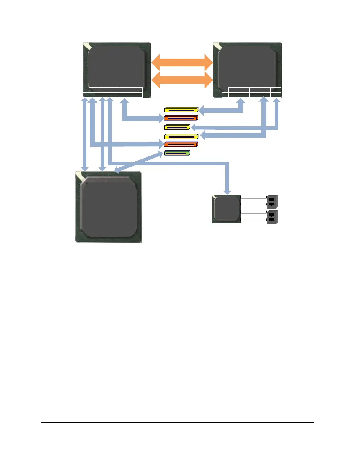
Figure 14. Functional Block Diagram of Processor IIO Sub-system
The following sub-sections will describe the server board features that are directly supported by
the processor IIO module. These include the PCI Card Slots, Network Interface, and connectors
for the optional SAS Module. Features and functions of the Intel
®
C600 Series chipset will be
described in its own dedicated section.
3.2.3.1 PCI Card Support
The server board provides six PCI card slots identified by PCIe Slot 1 to PCIe Slot 6. The PCIe
slot 1 is routed from Intel
®
C600 Series Chipset, The PCIe slot 2 and 5 are routed from CPU 1.
The PCIe slot 3, 4, 6 are routed from CPU 2.
Slot 1: PCIe Gen II x4 electrical with x8 physical connector, routed from Intel
®
C600
Chipset, support half-length card
Slot 2: PCIe Gen III x16 electrical with x16 physical connector, routed from CPU1,
support full length card
Slot 3: PCIe Gen III x16 electrical with x16 physical connector, routed from CPU2,
support full length, double width card

 Loading...


