Intel® Server Board S2600CO Family TPS On-board Connector/Header Overview
Revision 1.0
Intel order number G42278-002
8. On-board Connector/Header Overview
This section identifies the location and pin-out for on-board connectors and headers of the
server board that provide an interface to system options/features, on-board platform
management, or other user accessible options/features.
8.1 Power Connectors
The server board includes several power connectors that are used to provide DC power to
various devices.
8.1.1 Main Power
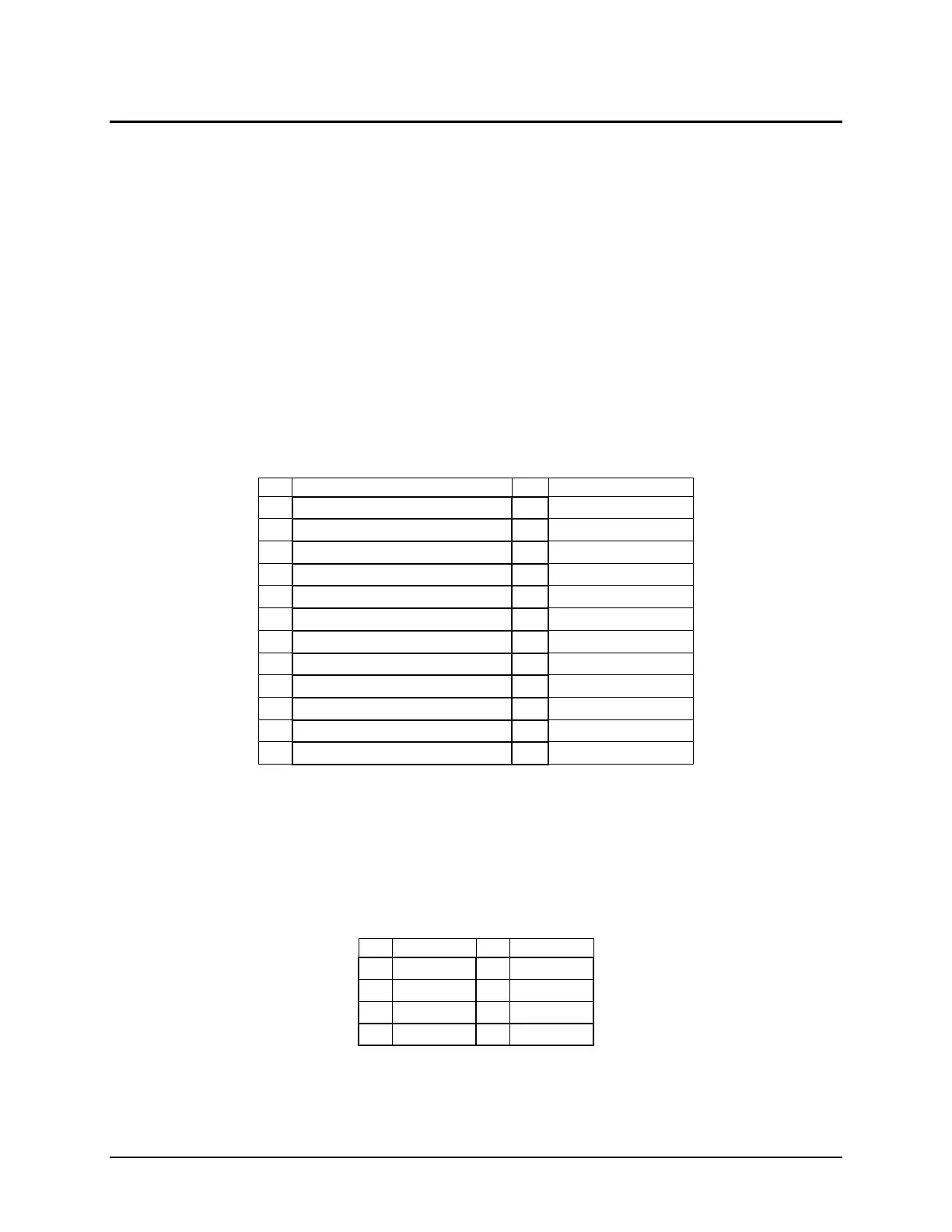
Main server board power is supplied from a 24-pin power connector. The connector is labeled
as “MAIN PWR” on the server board. The following tables provide the pin-out of “MAIN PWR”
connector.
Table 24. Main Power Connector Pin-out (“MAIN PWR”)
8.1.2 CPU Power Connectors
On the server board there are two white 8-pin 12V CPU power connectors labeled “CPU_1
PWR” and “CPU_2 PWR”. The following table provides the pin-out for both connectors.
Table 25. CPU Power Connector Pin-out (“CPU_1 PWR” and “CPU_2 PWR”)

 Loading...


