4-10 Return to Section Topics 2600AS-901-01 Rev. B / September 2008
Section 4: Source-Measure Concepts Series 2600A System SourceMeter® Instruments Reference Manual
Load considerations
The boundaries the SourceMeter instrument operates in depends on the load (DUT) that is
connected to its output.
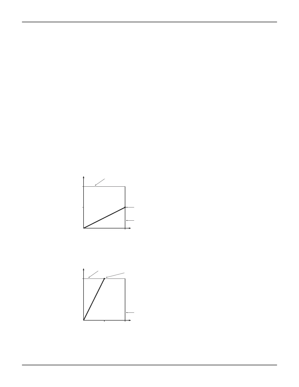
Figure 4-5 shows operation examples for resistive loads that are 50Ω and
200Ω, respectively. For these examples, the SourceMeter instrument is programmed to source
100mA and limit 10V.
In Figure 4-5A, the SourceMeter instrument is sourcing 100mA to the 50Ω load and subsequently
measures 5V. As shown, the load line for 50Ω intersects the 100mA current source line at 5V.
Figure 4-5B shows what happens if the resistance of the load is increased to 200Ω. The DUT load
line for 200Ω intersects the voltage compliance limit line placing the SourceMeter instrument in
compliance. In compliance, the SourceMeter instrument will not be able to source its programmed
current (100mA). For the 200Ω DUT, the SourceMeter instrument will only output 50mA (at the
10V limit).
Notice that as resistance increases, the slope of the DUT load line increases. As resistance
approaches infinity (open output), the SourceMeter instrument will source virtually 0mA at 10V.
Conversely, as resistance decreases, the slope of the DUT load line decreases. At zero resistance
(shorted output), the SourceMeter instrument will source 100mA at virtually 0V.
Regardless of the load, voltage will never exceed the programmed compliance
of 10V.
Figure 4-5
I-Source operating examples
Voltage Limit
Load Line
Operating
Point
Current Source
Load Line
I-Source (I
S
)
I-Source (I
S
)
V-Meter
(V
M
)
V-Meter
(V
M
)
5V
10V
100mA
50W DUT Load Line (R)
A) Normal I-source operation
Voltage Limit
Load Line
Operating
Point
Current Source
Load Line
10V
100mA
B) I-source in compliance
50mA
200W DUT Load Line (R)
V-Meter = I
S
R
= (100mA) (50W)
= 5V
I
S
= V
M
/ R
= 10V / 200W
= 50mA

 Loading...


