4: Theory of operation Series 2600B System SourceMeter® Instrument
4-4 2600BS-901-01 Rev. B / May 2013
When attempting to determine the maximum duty cycle, where the off state will be 0 V or 0 A:
I
B
is 0
I
P
and V
P
are the voltage and current levels when the instrument is on
Model 2601B/2602B/2604B maximum duty cycle equation constants
Constant 100 mV range 1 V range 6 V range 40 V range
Model 2611B/2612B/2614B/2634B/2635B/2636B maximum duty cycle equation
constants
Constant 200 mV range 2 V range 20 V range 200 V range
Operating boundaries
Source or sink
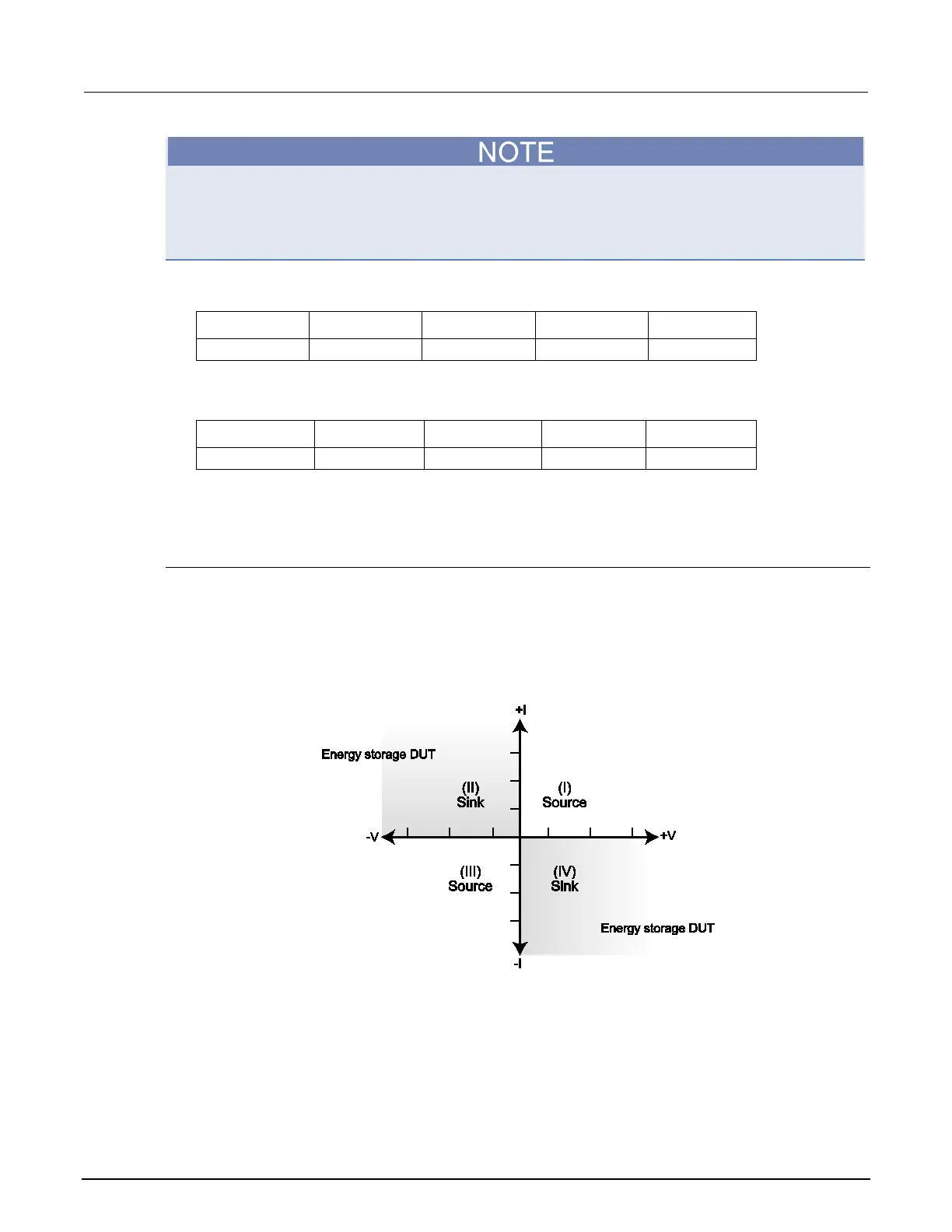
Depending on how it is programmed and what is connected to the output (load or source), the
instrument can operate in any of the four quadrants. The four quadrants of operation are shown in the
continuous operating boundaries figures. When operating in the first (I) or third (III) quadrant, the
instrument is operating as a source (V and I have the same polarity). As a source, the instrument is
delivering power to a load.
Figure 91: Four quadrants of operation
When operating in the second (II) or fourth (IV) quadrant, the instrument is operating as a sink (V and
I have opposite polarity). As a sink, it is dissipating power rather than sourcing it. An external source
or an energy storage device, such as a capacitor or battery, can force operation in the sink region.

 Loading...