Series 3700A System Switch/Multimeter Reference Manual Section 5: Switching and scanning
3700AS-901-01 Rev. D/June 2018 5-31
• scan.trigger.channel.clear() (on page 11-330)
• scan.trigger.channel.set() (on page 11-330)
• scan.trigger.channel.stimulus (on page 11-331)
• scan.trigger.clear() (on page 11-332)
• scan.trigger.measure.clear() (on page 11-333)
• scan.trigger.measure.set() (on page 11-333)
• scan.trigger.measure.stimulus (on page 11-334)
• scan.trigger.sequence.clear() (on page 11-335)
• scan.trigger.sequence.set() (on page 11-336)
• scan.trigger.sequence.stimulus (on page 11-336)
Hardware trigger modes
Use the hardware trigger modes to integrate Keithley Instruments and non-Keithley instruments into
an efficient test system. The hardware synchronization lines are classic trigger lines. The Series
3700A contains 14 digital I/O lines and three TSP-Link synchronization lines that you can use for
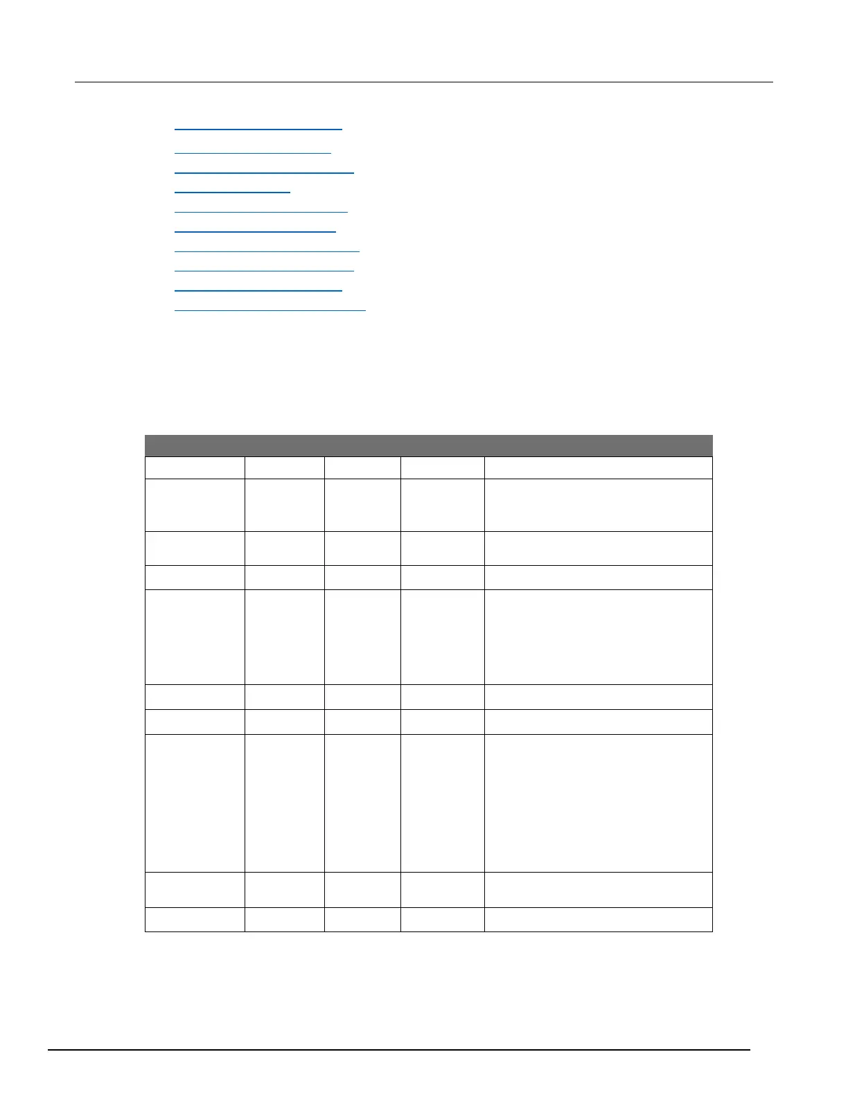
input or output triggering. The following table provides a summary for each hardware trigger mode.
Use the writebit and writeport
commands for direct line control
Short input pulses can cause a trigger
overrun
▪ The programmed state of the line
determines if the behavior is
similar to RisingA or RisingM
▪ High similar to RisingA
▪ Low similar to RisingM
▪ Behaves similar to
SynchronousA
▪ Trigger overrun detection is
disabled
▪ To mirror the SynchronousA
trigger mode, set the pulse
duration to 1 µs or any small
nonzero value
Ignores the pulse duration
Each trigger mode controls the input trigger detection and output trigger generation. The input
detector monitors for and detects all edges, even if the node that generates the output trigger causes
the edge.
 Loading...


