Commissioning
Process data to the axis module (control word Ctrl1 and setpoints)
6
131
EDBCSXM064 EN 11.0
6.9 Process data to the axis module (control word Ctrl1 and setpoints)
The control interface set under C4010 ( 130) is used to cyclically transmit process data
to the axis module.
Note!
ƒ For communication between master control (path control) and drive system,
only the process data channels CAN1_IN and CAN1_OUT of MotionBus
interface X4 are used.
The MotionBus (CAN) serves ...
– to synchronise the control cycle of the slaves to the one of the control
master,
– to transmit the master value,
– to control the drive and
– if required, to transmit the monitor data for diagnostic purposes.
ƒ The system bus interface X14 can only be used for parameter setting and
diagnostics with the Lenze parameter setting and operating program
"Global Drive Control" (GDC).
ƒ Further information on communication can be found in chapter
"8 Configuration" ( 196).
Structure of the process data transmitted to the axis module
User data
Byte 1 Byte 2 Byte 3 Byte 4 Byte 5 Byte 6 Byte 7 Byte 8
LOW byte HIGH byte LOW byte HIGH byte LOW word HIGH word
Word 1 Word 2 DWord (word 3 + word 4)
Control word Ctrl1
(C3152, C3153)
Only in "Velocity Mode":
Speed setpoint
Set position
(The set position is included in the double word1 and is
thus displayed in code C0867/1)
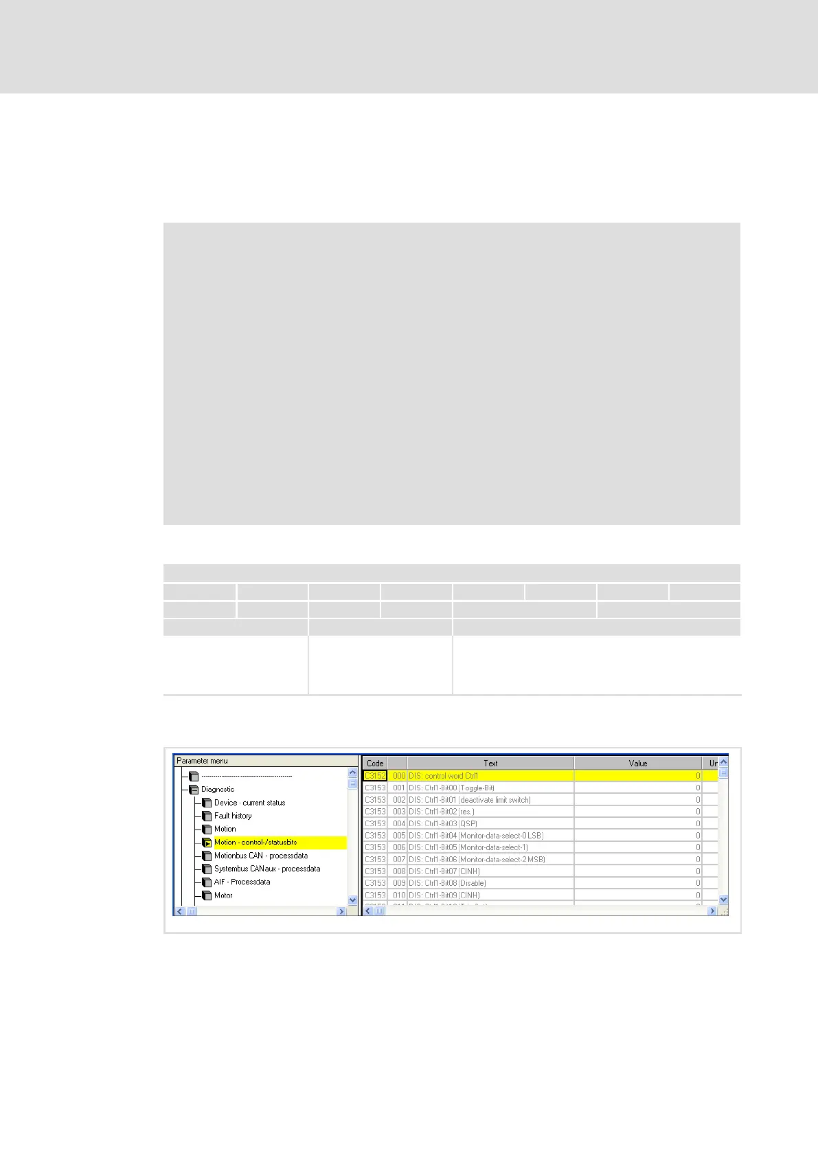
The GDC parameter menu includes codes for displaying the control word (C3152 and
C3153) under Diagnostics Control/status bits.
ECSXA534
Fig. 6−10 GDC view: Display of the control and status bits
 Loading...


