Electrical installation
Control terminals
Digital inputs and outputs
5
68
EDBCSXM064 EN 11.0
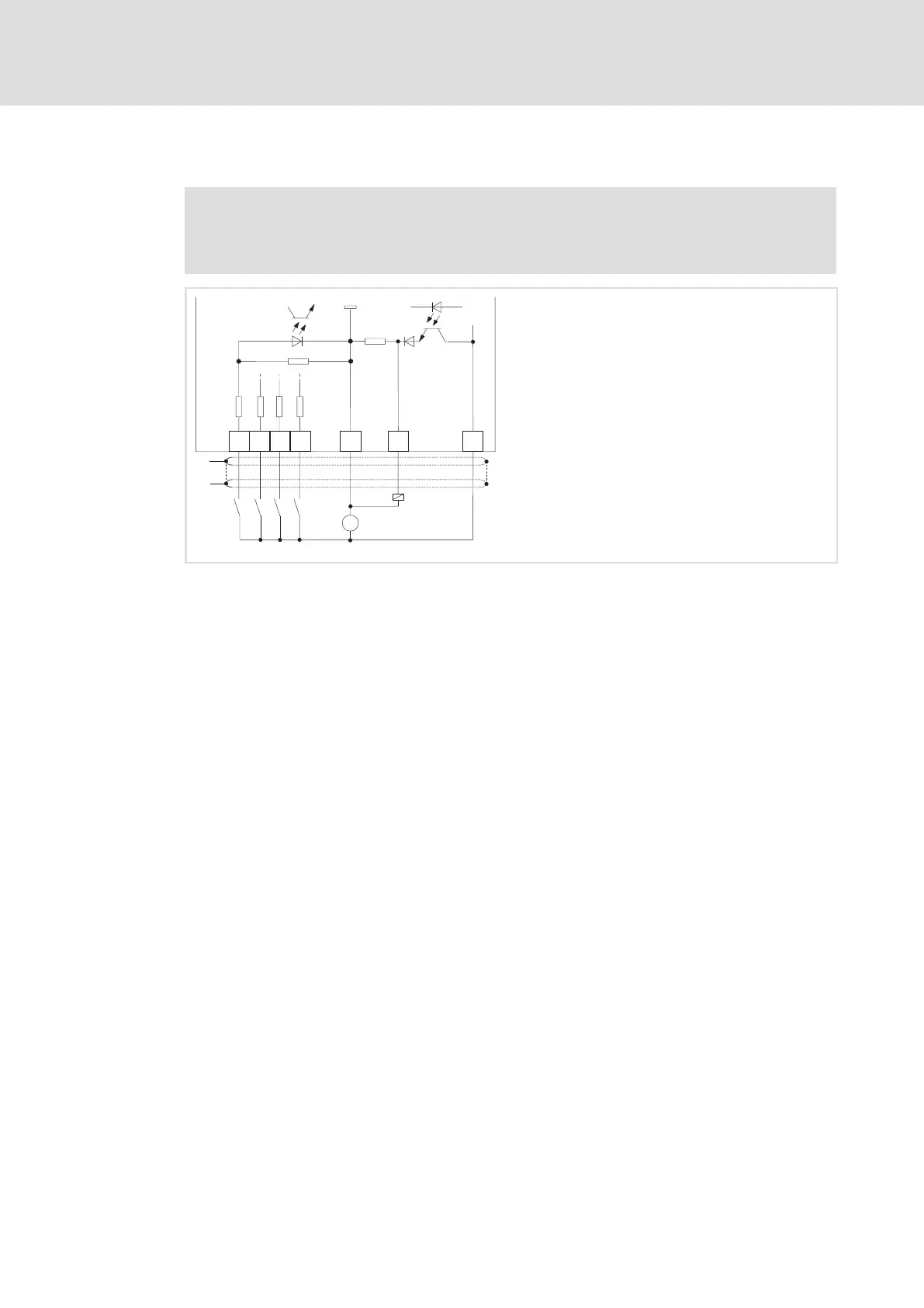
5.3.1 Digital inputs and outputs
Stop!
If an inductive load is connected to X6/DO1, a spark suppressor with a limiting
function to max. 50 V ± 0 % must be provided.
DI1
DI2
DI3
DI4
47k
GNDext
3k3
3k3
3k3
3k3
GND
DO1
X6
1.5 A
1k
+
_
24 VDC
=
+24
"
"
ECSXA014
Fig. 5−9 Digital inputs and outputs at X6
HF−shield termination by large−surface connection to functional earth (see Mounting
Instructions for ECSZS000X0B shield mounting kit)
ƒ The digital inputs X6/DI1 ... DI4 are freely assignable.
ƒ The polarity of the digital inputs X6/DI1 ... DI4 is set under C0114/x.
ƒ The polarity of the digital output (X6/DO1) is set under C0118/1.
 Loading...


