Electrical installation
Control terminals
5
64
EDBCSXM064 EN 11.0
5.3 Control terminals
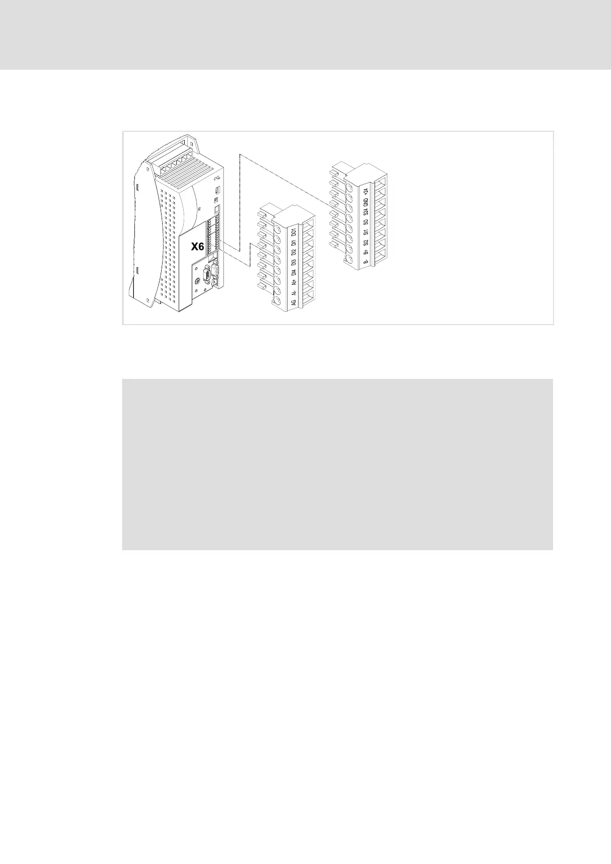
ECSXA070
Fig. 5−7 Plug connectors for control terminals (X6)
For the supply of the control electronics an external 24 V DC voltage at terminals X6/+24
and X6/GND is required.
Stop!
ƒ The control cables must always be shielded to prevent interference
injections.
ƒ The voltage difference between X6/AG, X6/GND and PE of the axis module
may maximally amount to 50 V.
ƒ The voltage difference can be limited by:
– overvoltage−limiting components or
– direct connection of X6/AG and X6/GND to PE.
ƒ The wiring has to ensure that for X6/DO1 = 0 (LOW level) the connected axis
modules do not draw energy from the DC bus. Otherwise, the power supply
module may be damaged.
 Loading...


