Electrical installation
Wiring of the feedback system
Digital frequency input/output (encoder simulation)
5
90
EDBCSXM064 EN 11.0
5.6.3 Digital frequency input/output (encoder simulation)
The digital frequency coupling of ECSxS/P/A axis modules basically is effected as a
master−slave connection via the interface X8. This interface can either be used as a digital
frequency input or as a digital frequency output (e. g. for encoder simulation)
(configuration via C0491).
Features
X8 as digital frequency input X8 as digital frequency output
l Input frequency: 0 ... 200 kHz
l Current consumption: max. 6 mA per channel
l Two−track with inverse 5 V signals and zero track
l Possible input signals:
– incremental encoder with two 5 V complementary
signals (TTL encoders) offset by 90°
l The function of the inputs signals can be set via
C0427.
l Output frequency: 0 ... 200 kHz
l Permissible current loading: max. 20 mA per
channel
l Two−track with inverse 5 V signals (RS422)
l The function of the output signals can be set via
C0540.
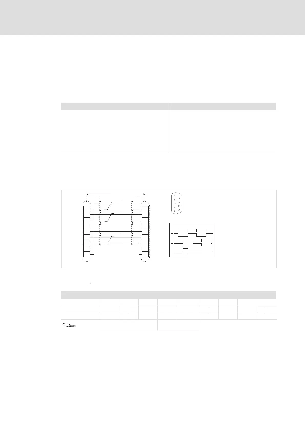
Wiring
ƒ 1 slave on the master:
Wire master and slave to each other directly via interface X8.
B
GND
Z
1
2
3
4
5
6
7
8
9
1
2
3
4
5
6
7
8
9
A
<50m
A
B
Z
A
A
B
Z
B
Z
X8
(ECS-Slave)
X8
(ECS-Master)
5
1
9
6
ECSXA029
Fig. 5−21 Connection of the master frequency input/output X8 (master « slave)
Signals for clockwise rotation
Cores twisted in pairs
Assignment of plug connector X8: Sub−D 9−pole
Pin 1 2 3 4 5 6 7 8 9
Input signal B A A ˘ GND Z Z ˘ B
Output signal B A A ˘ GND Z Z ˘ B
0.14 mm
2
(AWG 26)
1 mm
2
(AWG 18)
0.14 mm
2
(AWG 26)
 Loading...


