Electrical installation
Control terminals
Analog input
5
69
EDBCSXM064 EN 11.0
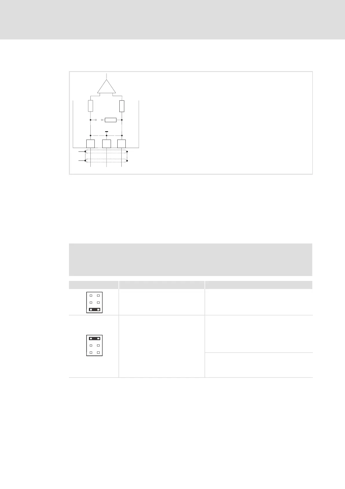
5.3.2 Analog input
AI-
AG
AI+
GND
82k5
X6
=
=
82k5
250R
X3
5
6
3.3 nF
3.3 nF
"
"
ECSXA015
Fig. 5−10 Analog input at X6
HF−shield termination by large−surface connection to functional earth (see Mounting
Instructions for ECSZS000X0B shield mounting kit)
Analog input configuration
ƒ Use C0034 to set whether the input is to be used for a master voltage (±10 V) or a
master current (+4 ... 20 mA or ±20 mA).
ƒ Set jumper bar X3 according to the setting in C0034:
Stop!
Do not plug the jumper on the pins 3−4! The axis module cannot be initialised
like this.
Jumper bar X3 Setting Measuring range
6
4
2
5
3
1
5−6 open
Jumper on 1−2: Parking position
C0034 = 0 (master voltage)
l Level: −10 ... +10 V
l Resolution: 5 mV (11 bits + sign)
l Scaling: ±10 V º ±16384 º ±100 %
6
4
2
5
3
1
5−6 closed
C0034 = 1 (master current)
l Level: +4 ... +20 mA
l Resolution: 20 mA (10 bits without sign)
l Scaling:
+4 mA º 0 º 0 %
+20 mA º 16384 º 100 %
C0034 = 2 (master current)
l Level: −20 ... +20 mA
l Resolution: 20 mA (10 bits + sign)
l Scaling: ±20 mA º ±16384 º ±100 %
 Loading...


