Configuration
Function blocks
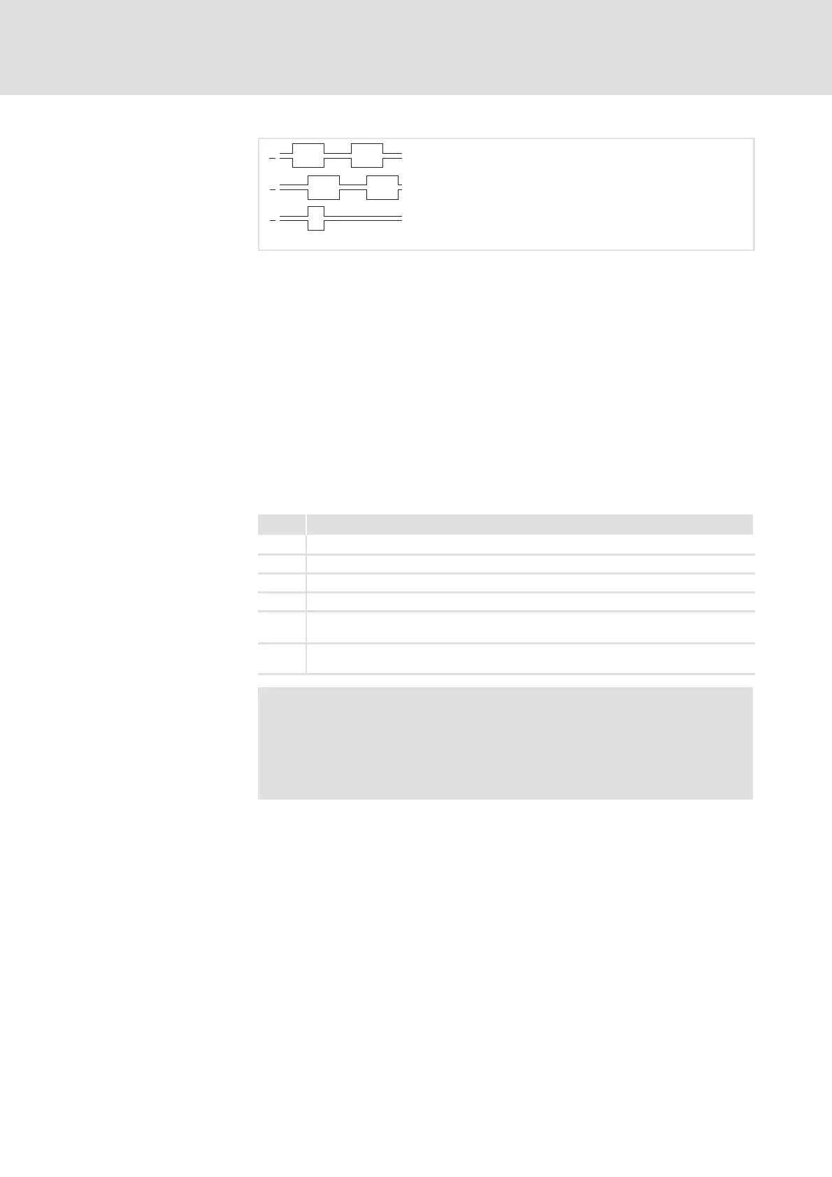
Master frequency output (DFOUT)
8
8.2
8.2.3
8.2-10
EDSVF9333V EN 3.0-06/2005
A
A
B
Z
B
Z
fb_dfout_01
Fig. 8.2-8 Signal sequence for CW rotation (definition)
ƒ The output signals correspond to the simulation of an incremental
encoder:
– Track A and track B and, if required, the zero track and the
corresponding inverted tracks are output. The levels are
TTL-compatible.
– Positive input values (CW rotation) result in the represented signal
sequence.
ƒ With negative input values (CCW rotation) track B leads track A by 90 °.
ƒ The encoder constant of the encoder simulation is set in C0030.
C0540 serves to define which i nput signal or signal source shall be active.
The zero track is output according to the selected setting.
C0540 Signal at X10
0 DFOUT-AN-IN is output to X10. Zero track can be selected externally.
1 DFOUT-DF-IN is output to X10. Zero track can be selected externally.
2 No function
3 No function
4 The signal at input X9 is electrically amplified and directly output (C0030 is without
function)
5 The signal at input X8 is electrically amplified and directly output (C0030 is without
function)
Note!
ThesettingsC0540=0andC0540=1arenotpossiblewhena
connection to the master frequency input X9 (DFIN) was
established and an incremental encoder was connected via X8
(C0025 = 100, 110 ... 113).
Output signals at X10
 Loading...