DC-bus operation
Central supply (one supply terminal)
10
10.2
10.2-1
EDSVF9333V EN 3.0-06/2005
10.2 Central supply (one supply terminal)
L3
N
PE
L1
L2
L1 L2
L3
F1 F2
F3
9341 - 9343
PE
+UG -UG
Z1
K10
U
V
W
L1 L2
L3
PE
+UG -UG
PE
U
V
W
M
3~
M
3~
PEPE
L1 L2
L3
PE
+UG -UG
PE
F4
F5
F6
F7
F8 F9
Z2
X1 X2
9321-9333
9321-9333
9300vec152
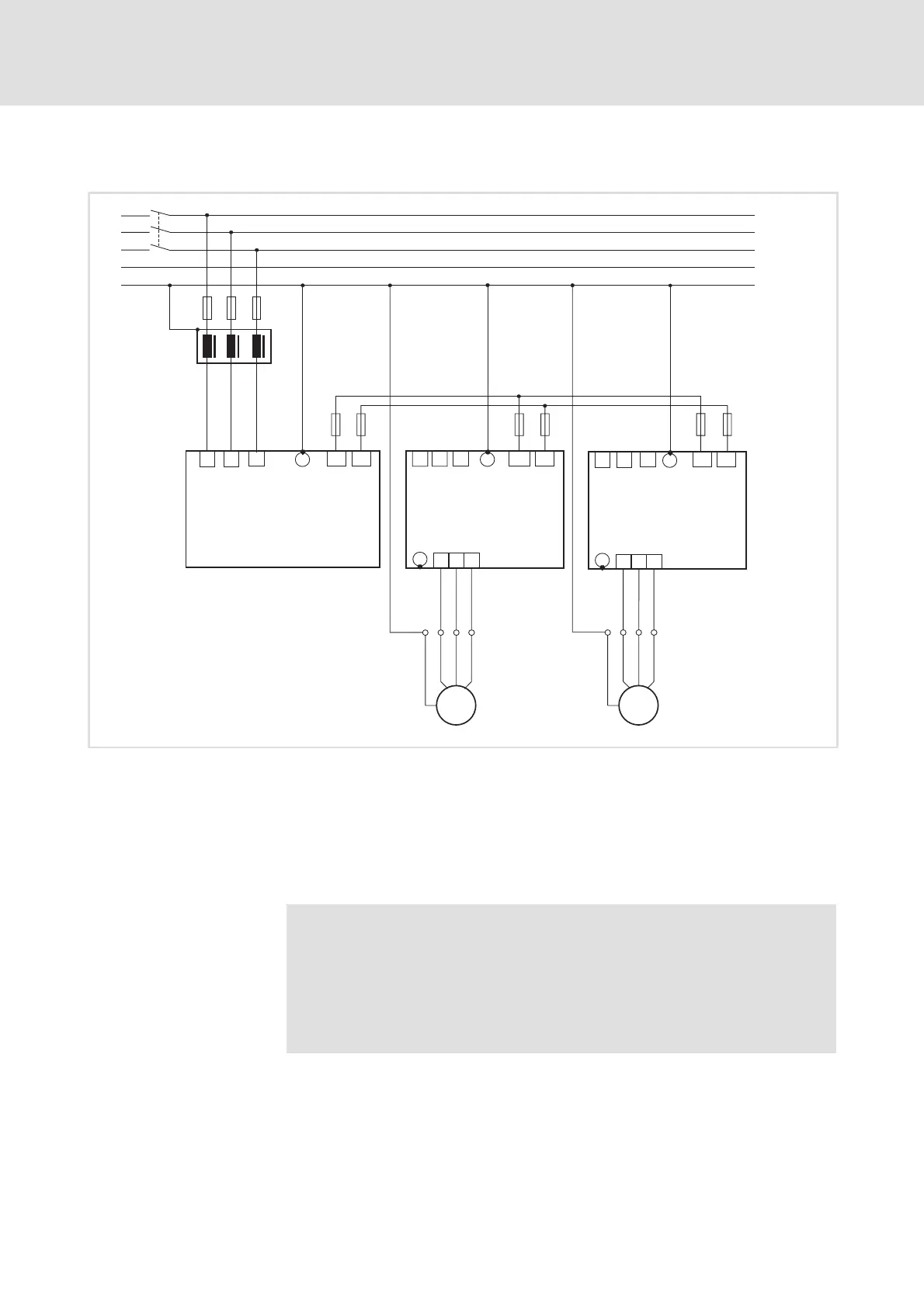
Fig. 10.2-1 Block diagram of a central supply with regenerative power supply module
F1 ... F9 Fuses
K10 Mains contactor
Z1 Mains filter
Z2 Regenerative power supply module
ƒ Design the components according to the requirements of the DC-bus
operation.
Note!
ƒ If the supply power of the regenerative power supply module
is not sufficient, the system can be additionally supplied in
parallel via the mains connection of further controllers.
ƒ Before connecting the controllers read the Operating
Instructions of the regenerative power supply module.
 Loading...