3.4.- UNIT TERMINALS
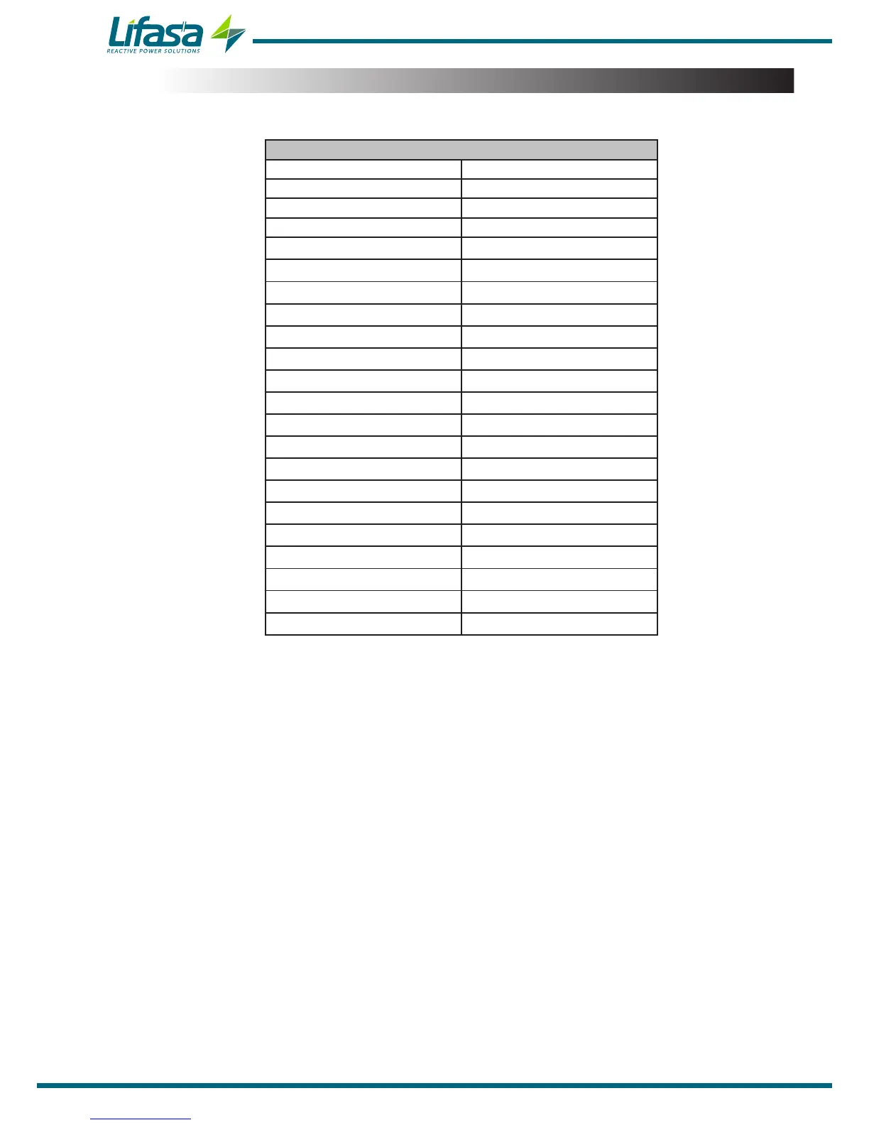
Table 2:List of Controller MASTER control VAR FAST terminals�
Terminals of the top side of the unit
1: A1,
Auxiliary power supply. 23: 8, Output 8
(1)
2: A2,
Auxiliary power supply. 24: 9, Output 9
(1)
3: V
L1
, L1 voltage input 25: 10, Output 10
(1)
4: V
L2
, L2 voltage input 26: 11, Output 11
(1)
5: V
L3
,L3 voltage input 27: 12, Output 12
(1)
6: V
LN,
Neutral voltage input
28: A(+), RS-485
7: S1,
L1 current input
29: B(-), RS-485
8: S2, L1 current input
30: S, GND for RS-485
9: S1,
L2 current input
31: 1, Digital input 1
10: S2, L2 current input
32: 2, Digital input 2
11: S1,
L3 current input
33: C, Digital inputs common
12: S2, L3 current input
34: 1, Digital output 1
13: S1,
Leakage current input
35: 2, Digital output 2
14: S2, Leakage current input
36: C, Digital outputs common
15: COM, Outputs common
37: Fan relay output
16: 1, Output 1
38: Fan relay output
17: 2, Output 2
39: NC, Alarm relay output
18: 3, Output 3
40: C, Alarm relay output
19: 4, Output 4
41: NO, Alarm relay output
20: 5, Output 5
42: A(+), CPC-NET
21: 6, Output 6
43: B(-), CPC-NET
22: 7, Output 7
(1)
44: S, GND for CPC-NET
(1)
Model Controller MASTER control VAR FAST 12
12

 Loading...
