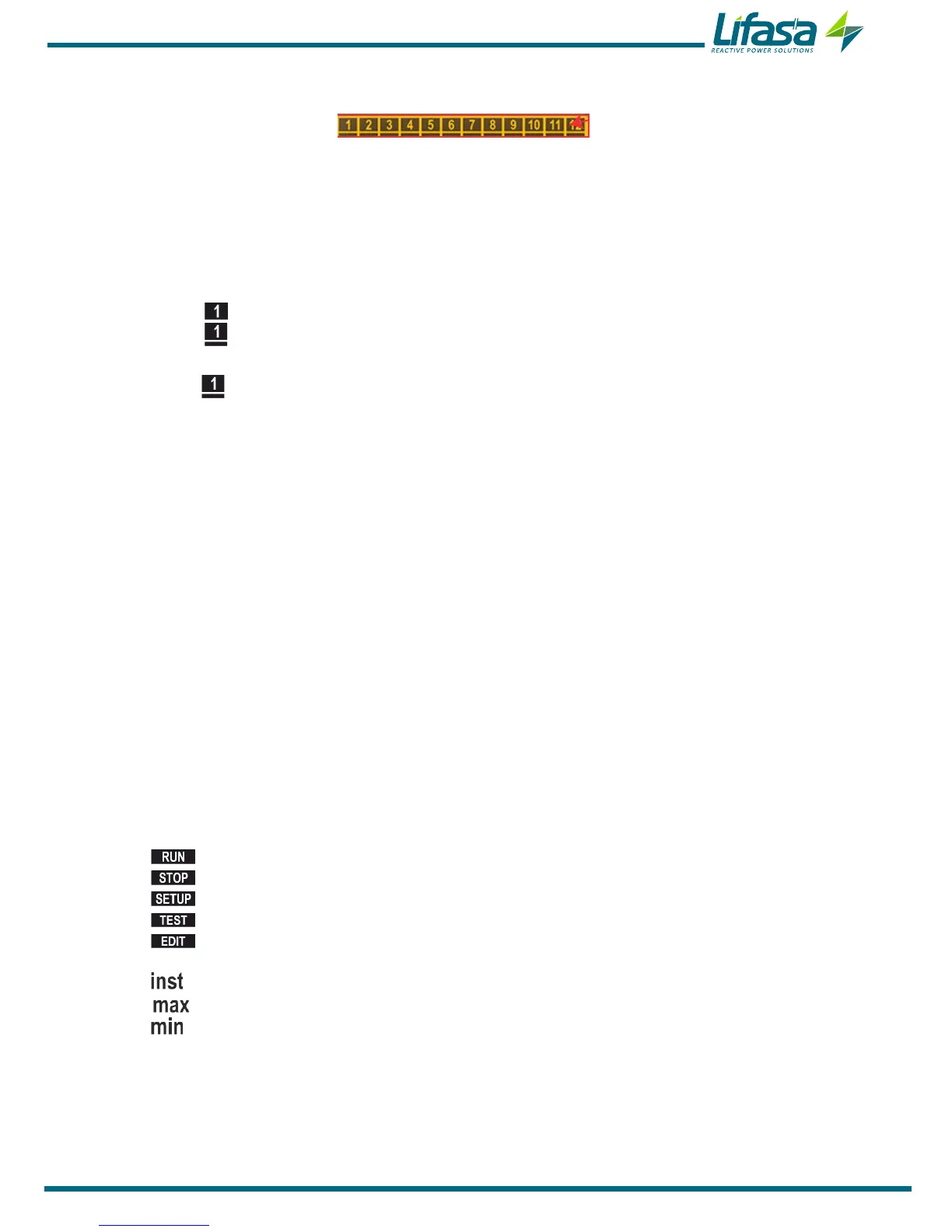
Figure 13: Status of the capacitors�
This area shows the status of the relays (stages) of the unit, and thus of the capacitors con-
nected to it.
The possible states are:
Nothing is displayed if the stage is not connected and congured as AUTO.
The icon is displayed if the stage is connected and congured as AUTO.
The icon is displayed with the bottom static bar if the stage is connected and con-
gured as On.
The icon is displayed with the bottom bar blinking if the stage is connected and
congured as On NC.
Only the static bottom bar is displayed if the stage is disconnected and configured as
OFF.
Only the blinking bottom bar is displayed if the stage is cancelled by the leakage cur-
rent alarm E15.
In the setup menu (“5.12.- STATUS OF THE STAGES”) the status of the stages is selected from
the following options:
AUTO: The status of the stage depends on the operation performed by the unit.
On: Stage forced to ON, always connected.
OFF: Stage forced to OFF, always disconnected.
On NC: Stage forced to ON, always connected but the system does not take into
account its connected power.
By default, all the stages are configured as AUTO.
4�4�2� STATUS OF THE UNIT
This area displays the status of the unit in accordance with the following icons:
The unit is in measurement and regulation mode.
The unit does not measure or regulate.
Indicates that you are in the setup menu.
Indicates that you are in the test menu.
Indicates that, within the setup menu, you are in editing mode.
Indicates that you are viewing the instantaneous value.
Indicates that you are viewing the maximum value.
Indicates that you are viewing the minimum value.
31

 Loading...
