4�10�1� MODBUS CONTROL FRAME
The Controller MASTER control VAR FAST controls the CPC3i boards using the MODBUS
protocol.
In particular, it sends a frame every 200 ms, using Function 15: N bits write.
The message is a "broadcast" message, i.e., it will be read by all boards, in any address.
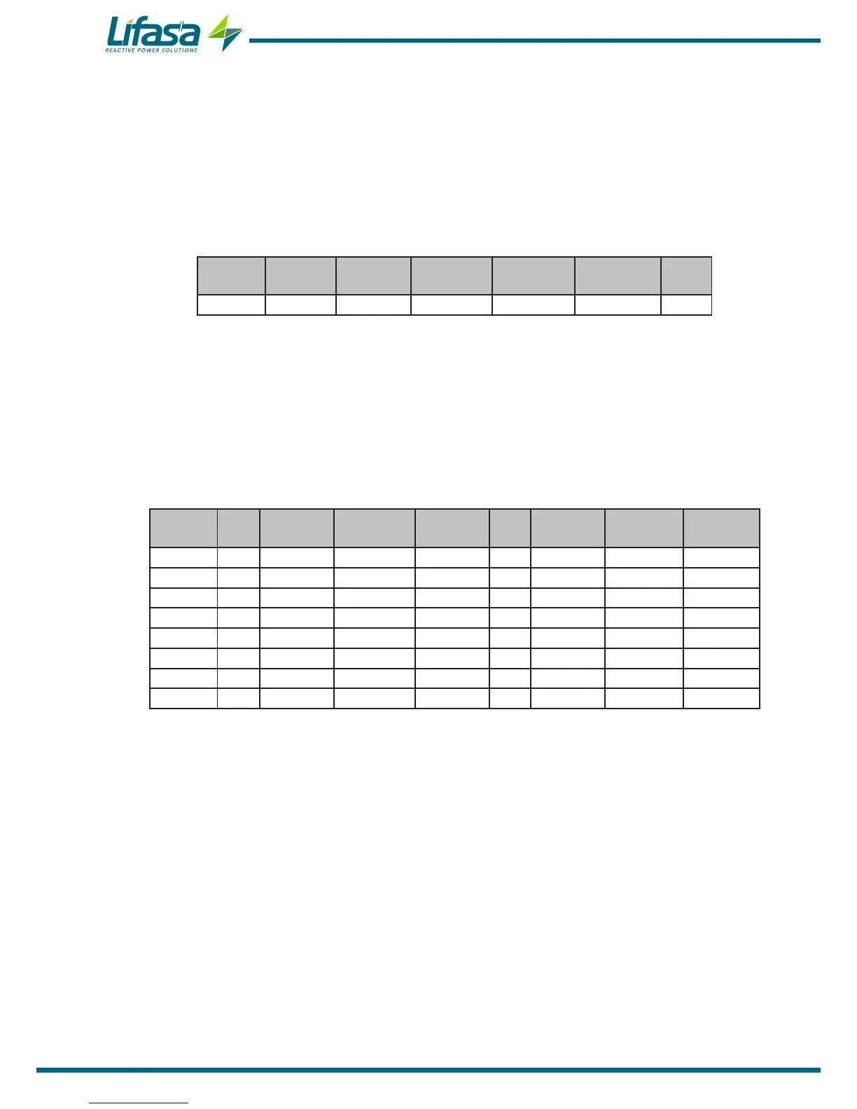
The format of the frame is as follows:
Address Function
Direction
of 1st bit
No� of bits No� of bytes Bits value CRC
00 0F 0064 0040 08 DD0 to DD7 XXXX
Address: 00, Broadcast, all the CPC3i boards receive all the frames.
Function: 0F, Write function.
Direction of 1st bit: 0064, the direction of the 1st bit in the CPC3i board is 0x0064.
No� of bits: 0040, the frame has 64 bits.
No� of bytes: 08, grouped into 8 byes.
Bits value: The meaning of the 8 bytes is detailed in Table 39.
CRC: XXXX, CRC character.
Table 39: Meaning of the 8 bytes, DD0 - DD7�
Byte Bit 7 Bit 6 Bit 5 Bit 4 Bit 3 Bit 2 Bit 1 Bit 0
DD0 - thy3_np2 thy2_np2 thy1_np2 - thy3_np1 thy2_np1 thy1_np1
DD1 - thy3_np4 thy2_np4 thy1_np4 - thy3_np3 thy2_np3 thy1_np3
DD2 - thy3_np6 thy2_np6 thy1_np6 - thy3_np5 thy2_np5 thy1_np5
DD3 - thy3_np8 thy2_np8 thy1_np8 - thy3_np7 thy2_np7 thy1_np7
DD4 - thy3_np10 thy2_np10 thy1_np10 - thy3_np9 thy2_np9 thy1_np9
DD5 - thy3_np12 thy2_np12 thy1_np12 - thy3_np11 thy2_np11 thy1_np11
DD6 - thy3_np14 thy2_np14 thy1_np14 - thy3_np13 thy2_np13 thy1_np13
DD7 - thy3_np16 thy2_np16 thy1_np16 - thy3_np15 thy2_np15 thy1_np15
thyn_npx means thyristor n of the block or peripheral x (This number of peripheral, x, is the
one programmed in the rotating selector for each board).
Note: The frame asks for the transmission of data to thyristors in up to 16 different steps,
phase by phase. The Controller MASTER control VAR FAST regulator has a maximum of
12 outputs, so it does not use the last 4 steps of the frame.
70

 Loading...
