4.6.- OPERATING STATES
The Controller MASTER control VAR FAST has 2 operating states with the display screens
matching the selected status:
Measurement status, ,
Test status, ,
4�6�1� MEASUREMENT STATUS
This status is identied by the symbol in the unit status area of the display (Figure 12).
It is the normal operating status of the Controller MASTER control VAR FAST, in which the
unit measures the various grid parameters and acts according to the congured parameters,
connecting or disconnecting the capacitors from the capacitor bank.
Use keys and to browse the various screens.
Delete maximum values:
On the maximum value display screen, press the key for more than 3 seconds.
Delete minimum values:
On the minimum value display screen, press the key for more than 3 seconds.
If 5 minutes pass without any keys being pressed, the unit returns to the main screen.
The display screens vary according to the connection type of the installation.
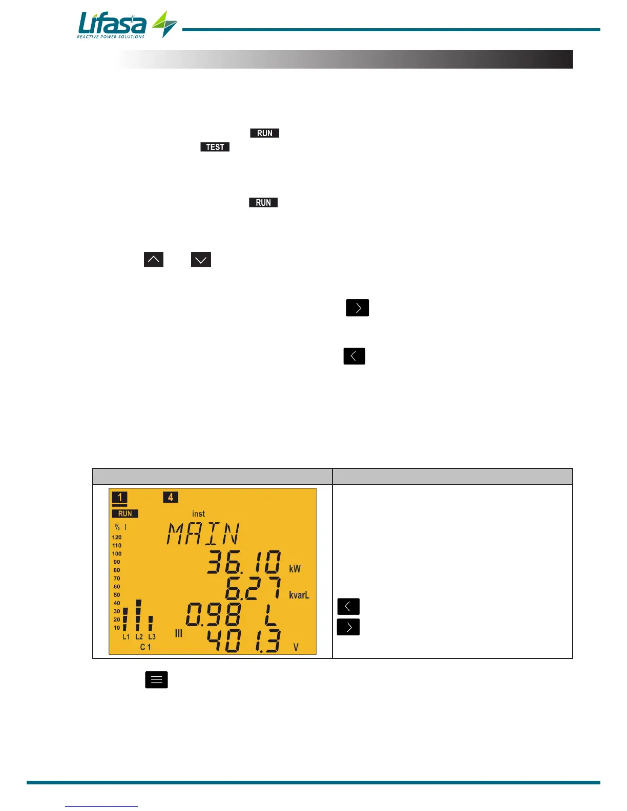
4�6�1�1� 3U.3C Connection (3 Voltages + Neutral and 3 currents)
Main Screen Parameters
Active Power III(kW or MW)
Reactive Power III(kvar or Mvar)
Cos φ
L: Inductive / C: capacitive
+: consumed / -: generated
Phase - Phase Voltage III(V or kV)
Display the minimum values.
Display the maximum values.
Press the key to switch to the Currents screen.
34

 Loading...
