Home
Lifasa
Controller
MASTER control Var
Lifasa MASTER control Var User Manual
4
of 1
of 1 rating
108 pages
Give review
Manual
Specs
To Next Page
To Next Page
To Previous Page
To Previous Page
Loading...
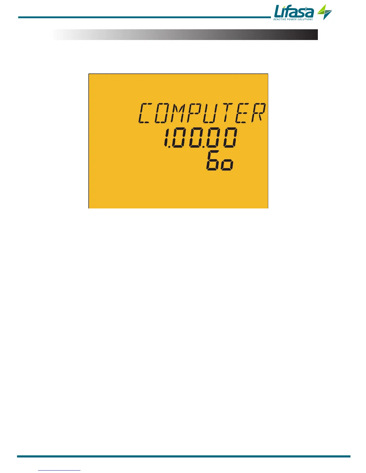
3.6.- ST
ARTING UP
THE UNIT
Once
the
Controller MASTER control V
AR F
AST
is
powered
on,
the
following
screen
appears
on the display
,
Figure 10
, which shows the name of the unit, the version and the model.
Figure 10: Controller MASTER control V
AR F
AST home screen�
After
a
few
seconds,
the
main
measurement
screen
appears.
21
Instruction Manual
Controller MASTER control V
AR F
AST
20
22
Table of Contents
Safety Precautions
3
Disclaimer
3
Table of Contents
4
Contents
4
Revision Log
6
1�- Verification Upon Reception
7
2�- Product Description
8
3�- Unit Installation
9
3�1�- Preliminary Recommendations
9
3�2�- Installation
10
3�4�- Unit Terminals
12
3�5�- Connection Diagram
14
3�5�1�- 3 Voltages + Neutral and 3 Currents, Controller Master Control Var
14
Fast 6 Model
14
3�5�2�- 3 Voltages + Neutral and 3 Currents, Controller Master Control Var
15
Fast 12 Model
15
3�5�3�- 3 Voltages + Neutral and 1 Current, Controller Master Control Var
16
Fast 6 Model
16
3�5�4�- 3 Voltages + Neutral and 1 Current, Controller Master Control Var
17
Fast 12 Model
17
3�5�5�- 2 Voltages and 1 Current, Controller Master Control Var Fast 6 Model
18
3�5�6�- 2 Voltages and 1 Current, Controller Master Control Var Fast 12 Model
19
3�5�7�- Leakage Current Connection, Iδ
20
3�6�- Starting up the Unit
21
4�- Operation
22
4�1�- Definitions
23
4�1�1 Four-Quadrant Regulator
23
4�1�2 Stages and Steps
23
4�1�3 FCP SYSTEM (FAST Computerized Program)
23
4�1�4 Regulation Program
23
4�1�5� Plug and Play
24
4�1�6 CONNECTION TIME (Ton) and RECONNECTION TIME (Trec)
24
4�1�7 Thd and Harmonics
24
4�2�- Measurement Parameters
25
4�2�1� Connection Type: 3U.3C
25
4�2�2� Connection Type: 3U.1C
26
4�2�3� Connection Type: 2U.1C
27
4�3�- Key Functions
28
4�4�- Display
30
4�4�1� Status of the Capacitors
31
4�4�2� Status of the Unit
31
4�4�3� Analogue Bar
32
4�4�4� Other Symbols on the Display
32
4�5�- Led Indicators
33
4�6�- Operating States
34
4�6�1� Measurement Status
34
4�6�2� Test Status
54
4�7�- Inputs
57
4�8�- Outputs
57
4�9�- Rs-485 Communications
58
4�9�1� Connections
58
4�9�2� Protocol
59
4�9�3� Modbus Memory Map
60
4�9�4� Example of a Modbus Query
68
4�10�- Cpc-Net Communications
69
4�10�1� Modbus Control Frame
70
5�- Configuration
71
5�1�- Plug&Play
72
5�2�- Current Transformation Ratio
75
5�3�- Target Cos
76
5�4�- Connection and Reconnection Time
77
5�5�- Connection Type
78
5�6�- Phase Connection
78
5�7�- No� of Stages
80
5�8�- Program
81
5�9�- C/K Factor
82
5�10�- Advanced Setup
84
5�11�- Voltage Transformation Ratio
85
5�12�- Status of the Stages
86
5�13�- Display
87
5�14�- Analogue Bar
88
5�15�- Fan
89
5�16�- Rs-485 Communications
90
5�17�- Cpc-Net Communications
91
5�18�- Clear
92
5�19�- Enabling Alarms
93
5�20�- Voltage Alarms
94
Alarm
95
COS Φ ALARM
95
5�22�- Voltage Thd Alarm
96
5�23�- CURRENT X I THD ALARM
97
5�24�- Temperature Alarm
98
5�25�- Leakage Current Alarm
100
5�26�- No� of Operations Alarm
101
5�27�- Simulation Screen
102
6�- Technical Features
103
7�- Maintenance and Technical Service
106
8�- Warranty
106
4
Based on 1 rating
Ask a question
Give review
Questions and Answers:
Need help?
Do you have a question about the Lifasa MASTER control Var and is the answer not in the manual?
Ask a question
Lifasa MASTER control Var Specifications
General
Brand
Lifasa
Model
MASTER control Var
Category
Controller
Language
English
Related product manuals
Lifasa MCE06ADV
18 pages
Lifasa PFCL Elite 6
32 pages

 Loading...
