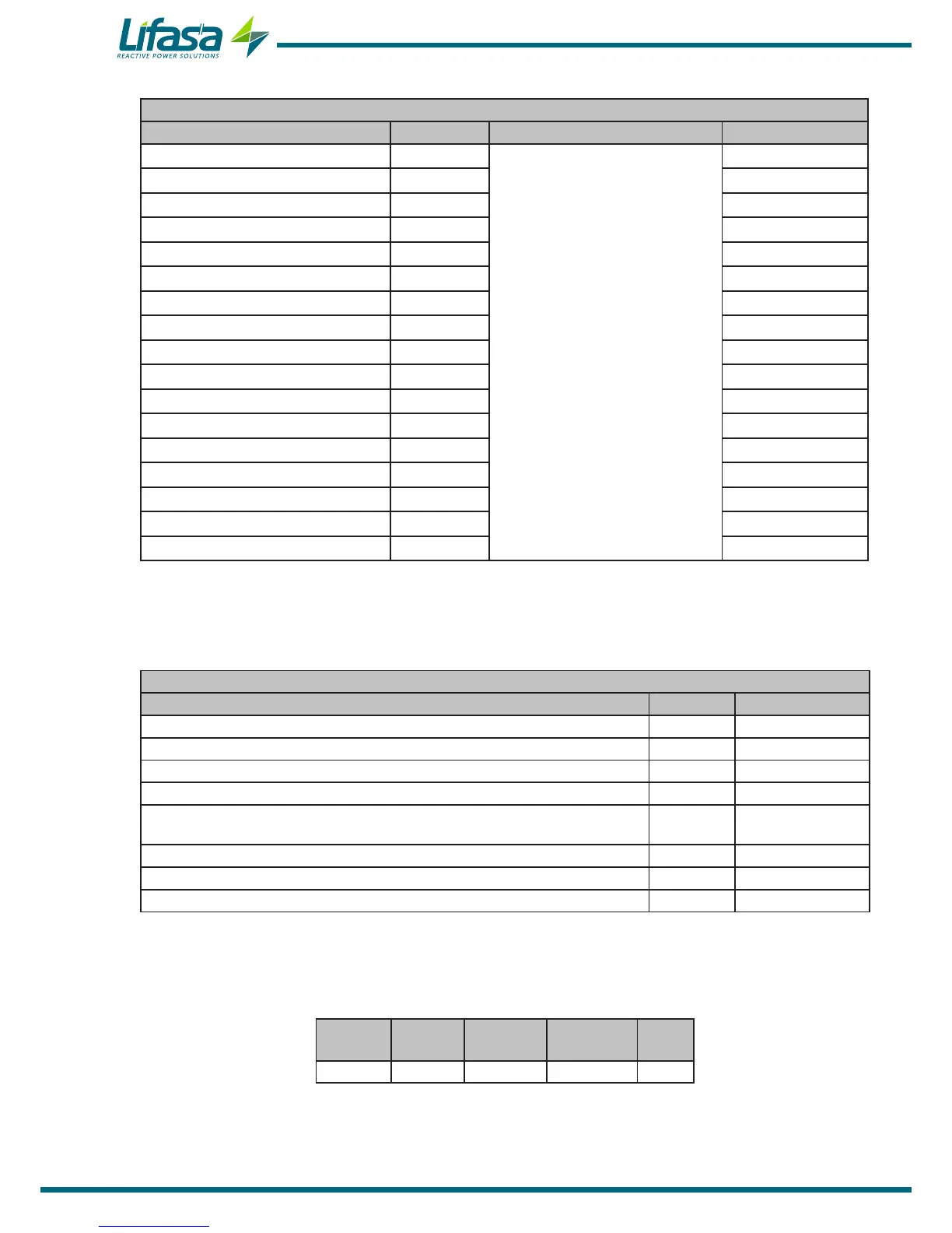
Table 36 (Continuation): Modbus memory map: programming variables (Table 22)
Enabling alarms
Configuration variable Address Valid data margin Default value
Output associated with Alarm E01 1170
0 (No),
1 (Alarm relay),
2 (Digital output 1)
2 (Digital output 2)
0
Output associated with Alarm E02 1171 0
Output associated with Alarm E03 1172 0
Output associated with Alarm E04 1173 0
Output associated with Alarm E05 1174 0
Output associated with Alarm E06 1175 0
Output associated with Alarm E07 1176 0
Output associated with Alarm E08 1177 0
Output associated with Alarm E09 1179 0
Output associated with Alarm E10 1179 0
Output associated with Alarm E11 117A 0
Output associated with Alarm E12 117B 0
Output associated with Alarm E13 117C 0
Output associated with Alarm E14 117D 0
Output associated with Alarm E15 117E 0
Output associated with Alarm E16 117F 0
Output associated with Alarm E17 1180 0
C.- Deleting parameters
Parameters can be deleted using Function 05: writing a relay.
Table 37:Modbus memory map: deleting parameters
Deleting parameters
Action Address Value to be sent
Deleting maximum values 200 FF
Deleting minimum values 210 FF
Deleting maximum and minimum values 220 FF
Deleting energies 230 FF
Deleting the stage search and stage enabling values of the leakage current
alarm
240 FF
Deleting the no. of operations of all the relays 250 FF
Resetting alarms E14 and E15 260 FF
Restoring the default conguration values 300 FF
4�9�4� EXAMPLE OF A MODBUS QUERY
Query: Instantaneous value of the L1 phase voltage
Address Function Initial log No� of logs CRC
0 A 04 0000 0002 70B0
Address: 0A, Peripheral number: 10 in decimal.
Function: 04, Read function.
68

 Loading...
