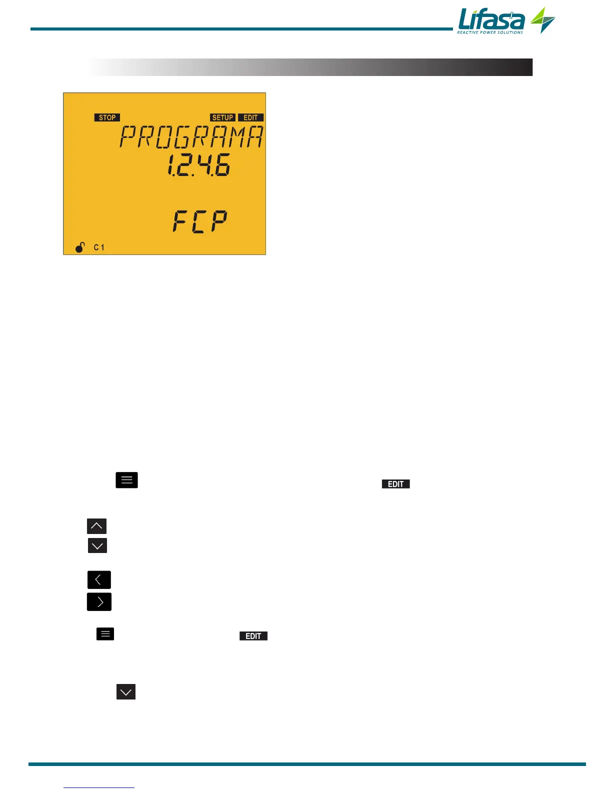
5.8.- PROGRAM
The unit is made up of stages with different powers.
The base power (value 1) will be that of the stage
with the lowest power. The powers of all the other
stages will depend on the power of the first stage.
Example:
Program 1�1�1�1, all the stages have the same
power as the first one.
Program 1�2�4�4, the second stage has twice the
power and the next ones have four times the power
of the first one. (See “4.1.4 Regulation program”)
When configuring the program, remember that the subsequent stage cannot be lower than the
prior stage, and that the first stage is always 1.
Also program the system that controls the connection sequence of the different stages, where:
FCP, operation following the FCP (“4.1.3 FCP System (FAST Computerized
Program)”)
TOTAL, total operation where all the steps are connected or disconnected at the same
time, without following a sequence; This operation is faster than the FCP.
SIM, no operation, the unit stays in simulation mode
(1)
.
(1)
In SIM mode, the measurement screens simulate the outputs that the unit would connect or
disconnect, but it doesn't actually do so. To avoid confusion, on the measurement screens the
name of the screen is switched with the literal Mode S
.
Press the key to enter editing mode. It is identified by the symbol and the blinking
of the digits to be modified.
The key increases the digit value.
The key decreases the digit value.
The key skips to the previous digit.
The key skips to the next digit.
Press to validate the data; the symbol disappears from the display.
Minimum value: 1.1.1.1
Maximum value: 1.9.9.9
Press the key to access the next programming step.
If no keys are pressed for 5 minutes, the unit switches to the simulation screen, “5.27.-
SIMULATION SCREEN”.
81

 Loading...
