Press the key to access the next programming step.
If no keys are pressed for 5 minutes, the unit switches to the simulation screen, “5.27.-
SIMULATION SCREEN”.
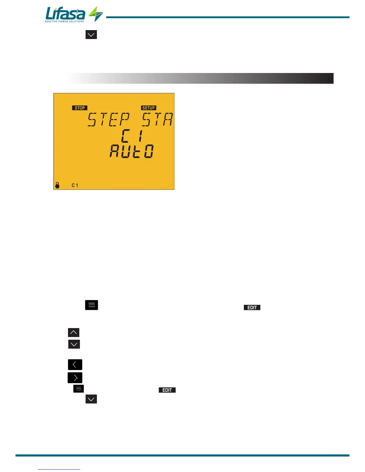
5.12.- STATUS OF THE STAGES
This parameter is repeated for each of the 6 or 12
possible stages, offering the opportunity to force
their status without paying attention to the operation
performed by the actual unit.
In order to identify which of the 12 stages is being
configured, the screen shows C1, C2, etc.
The configuration options for each stage are as follows:
AUTO: The status of the stage depends on the operation performed by the unit.
On: Stage forced to ON, always connected.
OFF: Stage forced to OFF, always disconnected.
On NC: Stage forced to ON, always connected but the system does not take into
account its connected power.
By default, all the stages are configured as AUTO.
On the measurement screens, the forced states of the stages are shown by activating the
bottom line of the capacitor status bar. ( “4.4.1. STATUS OF THE CAPACITORS”)
Press the key to enter editing mode. It is identified by the symbol and the blinking
of the digits to be modified.
The key shows the next option.
The key shows the previous option.
The key skips to the previous stage.
The key skips to the next stage.
Press to validate the data; the symbol disappears from the display.
Press the key to access the next programming step.
If no keys are pressed for 5 minutes, the unit switches to the simulation screen, “5.27.-
SIMULATION SCREEN”.
86

 Loading...
