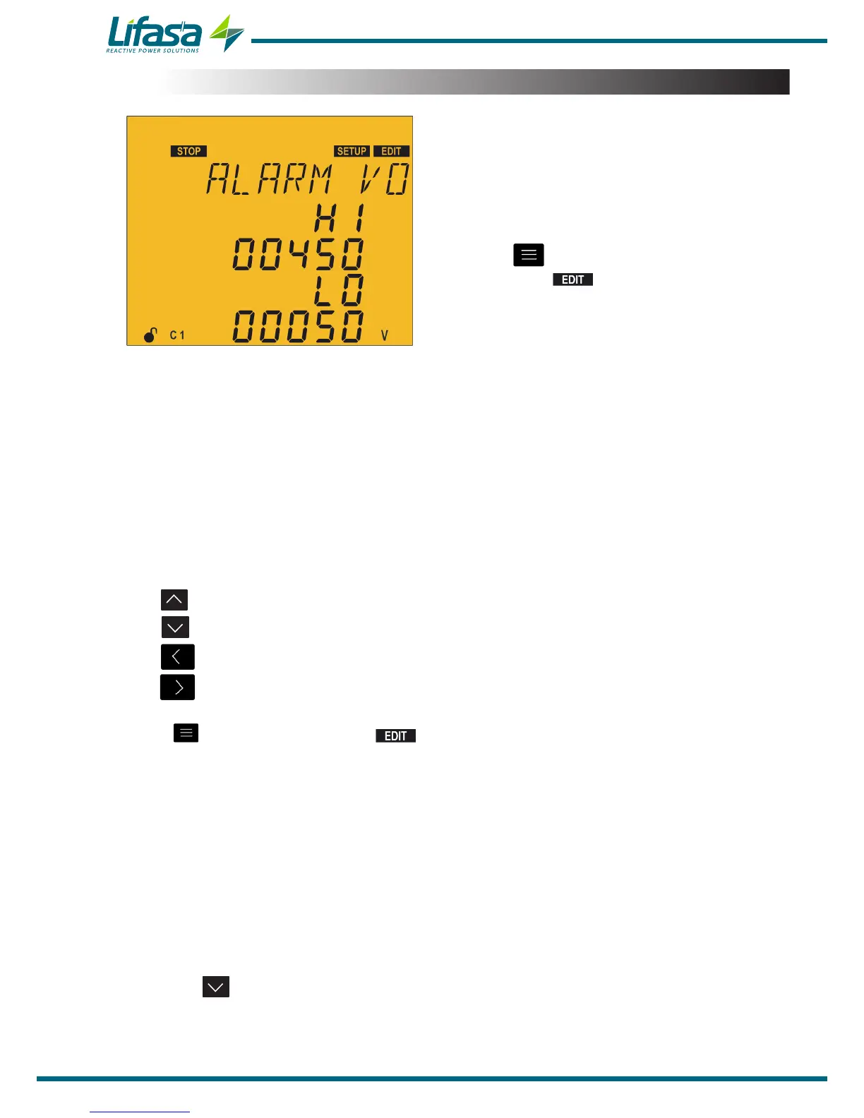
5.20.- VOLTAGE ALARMS
In this point the phase-phase voltage thresholds
above which the overvoltage alarm (E05) and the
no voltage alarm (E06) should be triggered can be
configured.
The alarm must be enabled (“5.19.- ENABLING
ALARMS”).
Press the key to enter editing mode. It is
identified by the symbol and the blinking of
the digits to be modified.
In order to avoid possible false activations of said alarms, they have a predefined delay of 5
seconds.
The parameters to be configured are:
The value of the overvoltage alarm: HI�
The value of the no voltage alarm: LO�
When any of the two alarms are triggered, the unit enters the Disconnection status and
disconnects all the stages. The unit does not return to its normal operating status until the
cause for the alarm disappears.
The key increases the digit value.
The key decreases the digit value.
The key skips to the previous digit.
The key skips to the next digit.
Press to validate the data; the symbol disappears from the display.
Overvoltage alarm:
Maximum value: 99999 V
Minimum value: 0 V
No voltage alarm:
Maximum value: 99999 V
Minimum value: 0 V
If the value entered is lower than the minimum value or higher than the maximum value,
the backlight of the display ashes and the value entered is replaced with the minimum or
maximum value, or with the last value validated.
Press the key to access the next programming step.
If no keys are pressed for 5 minutes, the unit switches to the simulation screen, “5.27.-
SIMULATION SCREEN”.
94

 Loading...
