Initial Log: 0000, log from which to start reading.
No� of logs: 0002, number of logs to be read.
CRC: 70B0, CRC character.
Response:
Address Function
No� of
Bytes
Log no� 1 Log No� 2 CRC
0 A 04 04 0000 084D 8621
Address: 0A, Responding peripheral number: 10 in decimal.
Function: 04, Read function.
No� of bytes: 04, No. of bytes received.
Log: 0000084D, value of the L1 phase voltage: VL1 x 10 : 212.5V
CRC: 8621, CRC Character.
4.10.- CPC-NET COMMUNICATIONS
Controller MASTER control VAR FAST series regulators are designed to control static capac-
itor banks where they can operate through optoMOS relay outputs or through communications.
If communications are used, they must be connected to CPC3i-xRS zero switching control
boards.
The Controller MASTER control VAR FAST connection with the board will be made through
the CPC-NET channel, in accordance with the connection table, Table 38. Also consult the ter-
minal diagrams in Figure 2 and Figure 18.
Table 38: Table showing the CPC3i to Controller MASTER control VAR FAST connection�
CPC3i-xRS
Controller MASTER control
VAR FAST
Function
Terminal Name Terminal Name
A SH 44 S Communication cable screen
B RS+ 42 A(+) Transmitter / Receiver +
C RS- 43 B (-) Transmitter / Receiver -
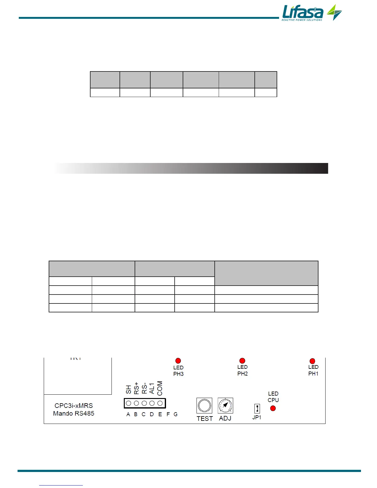
Each CPC3i board of a static capacitor bank must be congured with a different address (1 to
16) for each step, using a rotating ADJ switch with the CPC3i board. (Figure 18)
Figure 18:Terminals of the CPC3i-xRS board�
69

 Loading...
