4�4�3� ANALOGUE BAR
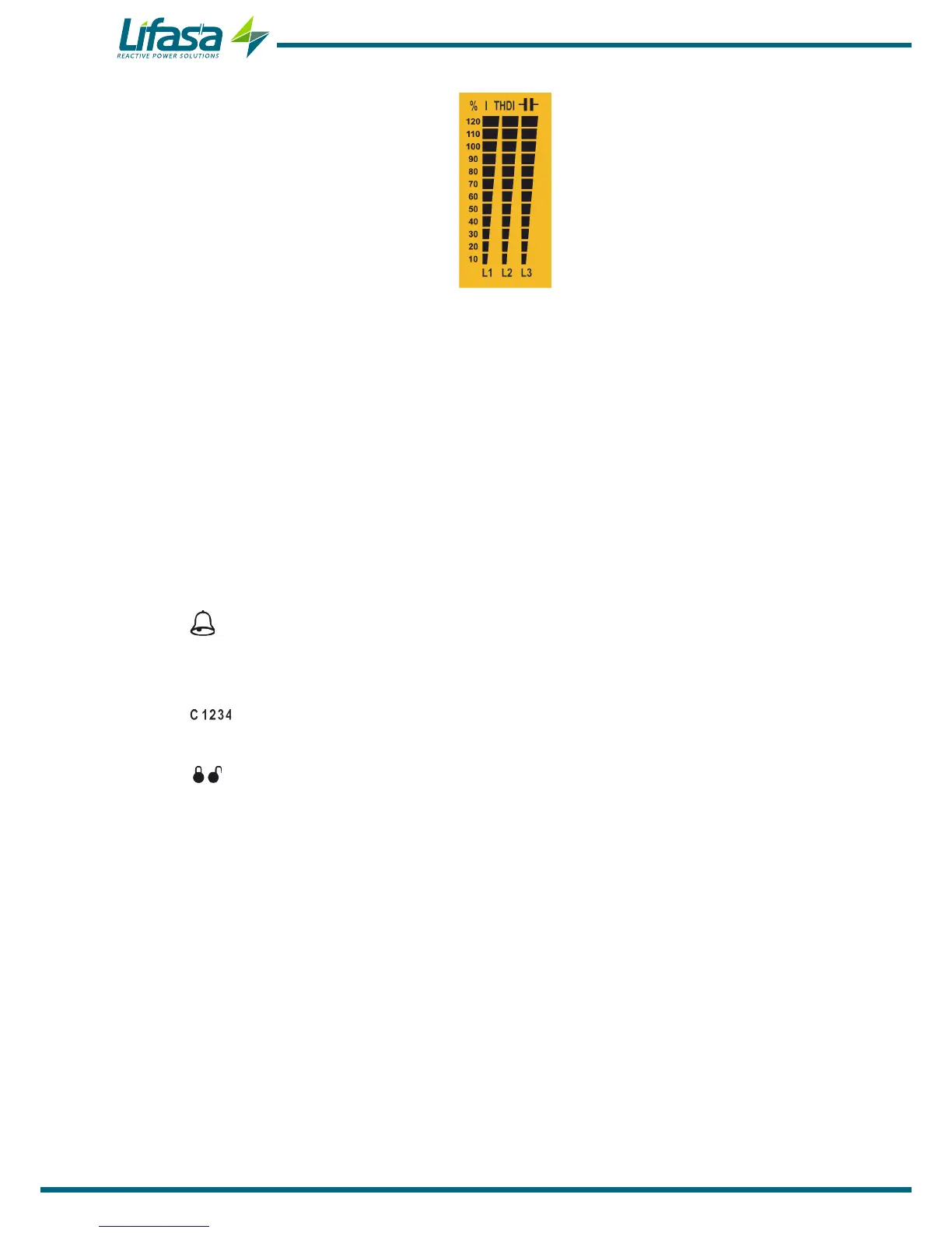
Figure 14: Analogue Bar
This bar is displayed on the measurement screens, and can show:
the current of each phase as a percentage.
the current THD of each phase.
the power connected to the capacitor bank.
The parameter to be displayed is selected in the setup menu. (“5.14.- ANALOGUE BAR”)
The display screen also shows the results of the TEST and the load % of the capacitors.
4�4�4� OTHER SYMBOLS ON THE DISPLAY
The display also shows the following:
Alarm: When the unit detects an alarm, the backlight of the display ashes and the
alarm icon lights up. The cause of the alarm can be seen on the active alarms screen.
("4.6.- OPERATING STATES”)
Target cosine: The icons indicate which one of the 4 possible target cosines has
been selected. (“5.3.- TARGET COS φ”)
Editing locked / unlocked: The editing of the programming parameters is password
protected. These icons indicate whether or not this option is locked.
32

 Loading...
