4.7.- INPUTS
The Controller MASTER control VAR FAST comprises two digital inputs (terminals 31 and 32
of Figure 2) for activating any of the four target cos φ, in other words, the desired power factor
for the installation, which can be programmed in the unit. See “5.3.- TARGET COS φ”
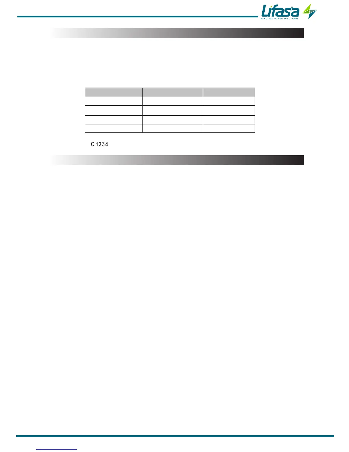
Table 10: Selection of the target cos φ.
Digital input 2 Digital Input 1
Target cos φ
0 0 1
0 1 2
1 0 3
1 1 4
On the display, the icon indicates which of the 4 possible target cosines was selected.
4.8.- OUTPUTS
The unit features:
A relay (terminals 37 and 38 of Figure 2) dedicated to activating a fan when a pre-de-
termined temperature is exceeded, which can be programmed in "5.15.- FAN”, is also
connected to the Fan LED.
A fully programmable alarm relay (terminals 39, 40 and 41 of Figure 2), see
“5.19.- ENABLING ALARMS”
Two digital outputs, fully programmable optoisolated NPN transistors (terminals 34,
35 and 36 of Figure 2 ), see “5.19.- ENABLING ALARMS”
Controller MASTER control VAR FAST 6 model:
Six optoMOS relay outputs (terminals 15 ...21 of Figure 2) for the regulation of cos φ
via capacitors.
Controller MASTER control VAR FAST 12 model:
Twelve optoMOS relay outputs (terminals 15 ...27 of Figure 2) for the regulation of
cos φ via capacitors.
57

 Loading...
