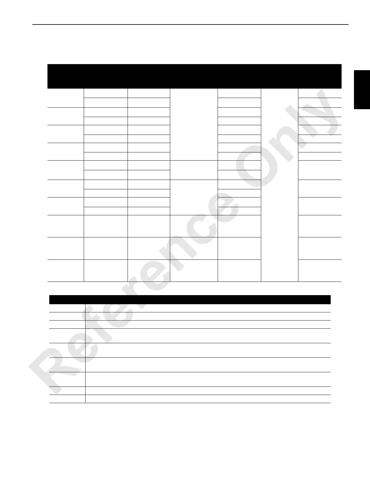
Function Direction Pump-Port
System
Pressure 1
1
psi (bar)
System
Pressure 2
2
psi (bar)
Charge
Pressure
Speed
3
rpm
Drum 1
Hoist
Pump 2 - B
8
6,090 (420) Up
3,770 (260) Down
NA
350 (24)
48 - 53
Lower/Accessory
Pump 2 - A
8
NA 42 - 50
Drum 2
Hoist
Pump 5 - B
8
NA
48 - 53
Lower Pump 5 - A NA 42 - 50
Drum 3
7
Up
Pump 3 - A
8
NA
39 - 43
Down Pump 3 - B NA 34 - 41
Drum 4
Up
Pump 4 - A
8
NA
39 - 43
Down Pump 4 - B NA 34 - 41
Swing
Left
Pump 6 - B
8
6,090 (420)
NA
2.3
Right
Pump 6 - A
8
NA
Right Crawler
Forward
Pump 1 - B
8
6,090 (420)
5,900 (407)
11 at
Tumbler
Reverse Pump 1 - A 5,900 (407)
Left Crawler
7
Forward
Pump 3 - A
8
5,900 (407)
11 at
Tumbler
Reverse Pump 3 - B 5,900 (407)
Low Pressure
Accessory
System
4
NA NA NA NA NA
High Pressure
Accessory
System
5
NA NA NA
600 (41) to
3.500 (241)
NA
Carbody
Control
System
6
NA NA NA 3,000 (207) NA
Notes
NA Not Applicable
1 Controlled by multi-function valves in each pump
2 Controlled by crane’s programmable controller
3
Speeds based on engine at high idle, no load (no rope on drums), and handles moved fully forward or back.
Speeds can very plus or minus 5%.
4
Swing brake, travel brakes, travel two speed, left travel/auxiliary hoist diverting valve, back hitch pins
disable, and boom hoist pawl
5
Live mast cylinders, gantry raise cylinders, boom hinge pins, cab tilt. Accessory system pressure is from low
pressure side of front drum pump #5. Computer controls pump pressure depending on accessory selected.
6
Crawler pins and carbody jacks (manual handles). System pressure is enabled with system pressure sender
and controlled by computer.
7 Pump used for left crawler or drum 3 (auxiliary) function. Computer selects first handle moved.
8 Pressure sender system port location. Travel system pressure sender is between each leg port.

 Loading...


