POWER TRAIN 14000 SERVICE MANUAL
7-12
Published 09-10-14, Control # 065-24
Current Production - Tier 3/4
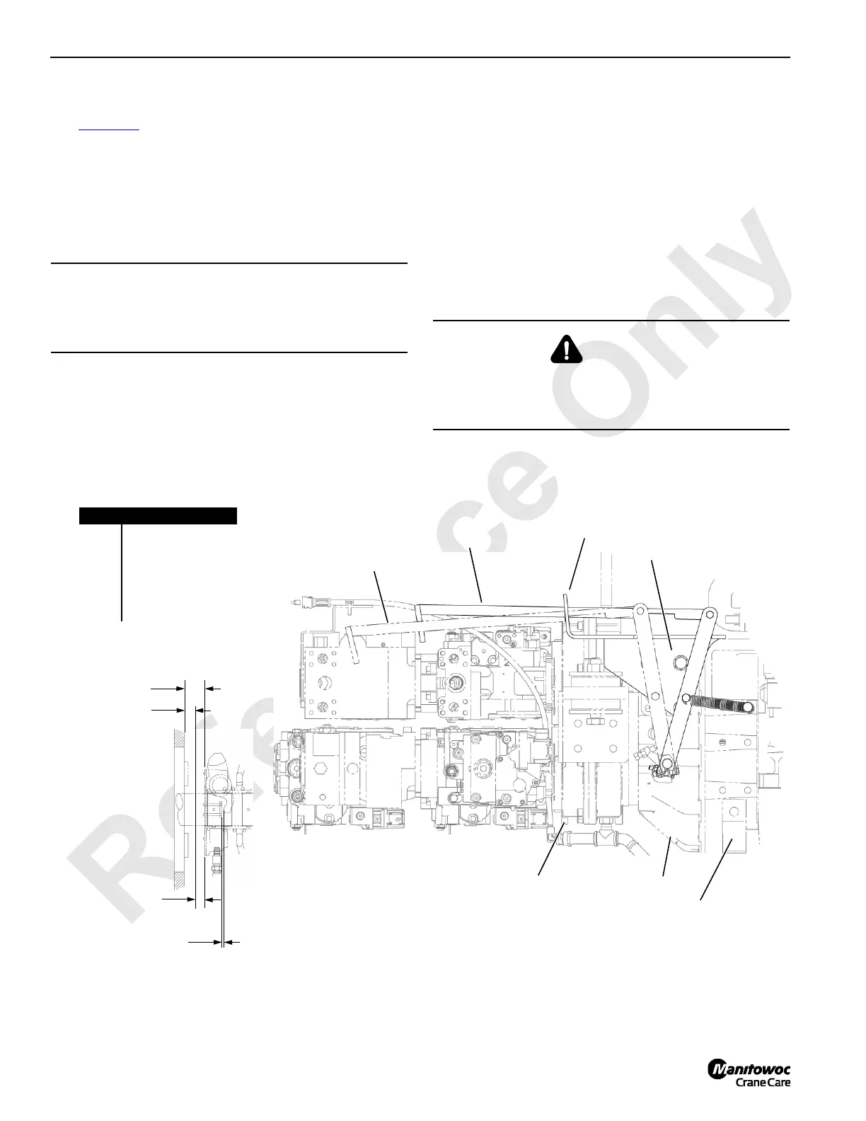
See Figure 7-7 for the following procedure.
A disc-type manually operated clutch is mounted between
the engine and the pump drive. The clutch allows the pump
drive to be disconnected from the engine, reducing engine
load and making start-up easier in cold weather. The clutch
can be engaged or disengaged while the engine is running or
stopped.
Operation
1. Grease clutch monthly. See Lubrication Folio 2129.
2. At least once each month, disengage and engage the
clutch several times with engine running. Ensure all
pawls and seizing locks are engaged before
disengaging clutch. This practice cleans disc surfaces
and prevent discs from seizing.
3. When disengaging clutch, check free travel. Free travel
should be 0.5 in (12,7 mm) and 0.56 in (14,2 mm). If not,
readjust. If less than 0.75 in (19 mm), adjust per clutch
manufacturer’s manual.
Adjustment
The clutch is adjusted internally through the hand hole on top
of the clutch housing. See the clutch manufacturer’s manual
for adjustment instructions.
CAUTION!
Parts Damage!
Do not run the engine longer than 20 minutes with clutch
disengaged. Clutch release bearing can be damaged.
DANGER!
Moving Machinery Hazard!
Parts inside clutch rotate when the engine is running. Stop
the engine before adjusting clutch.
FIGURE 7-7
View From Rear of Crane
Item Description
1 Handle
2Latch
3 Engine
4Clutch
5 Hand Hole Cover
6 Pump Drive
1 – DISENGAGED
1 – ENGAGED
3
2
4
6
4
Engaged
Disengaged
0.5 in (12.7 mm) to
0.56 (14.2 mm)
Release Travel
Free Travel Between
Yoke and Wear Pads
0.13 in (3,3 mm)
Clutch
Adjustment

 Loading...


