Manitowoc Published 09-10-14, Control # 065-24 4-7
14000 SERVICE MANUAL BOOM
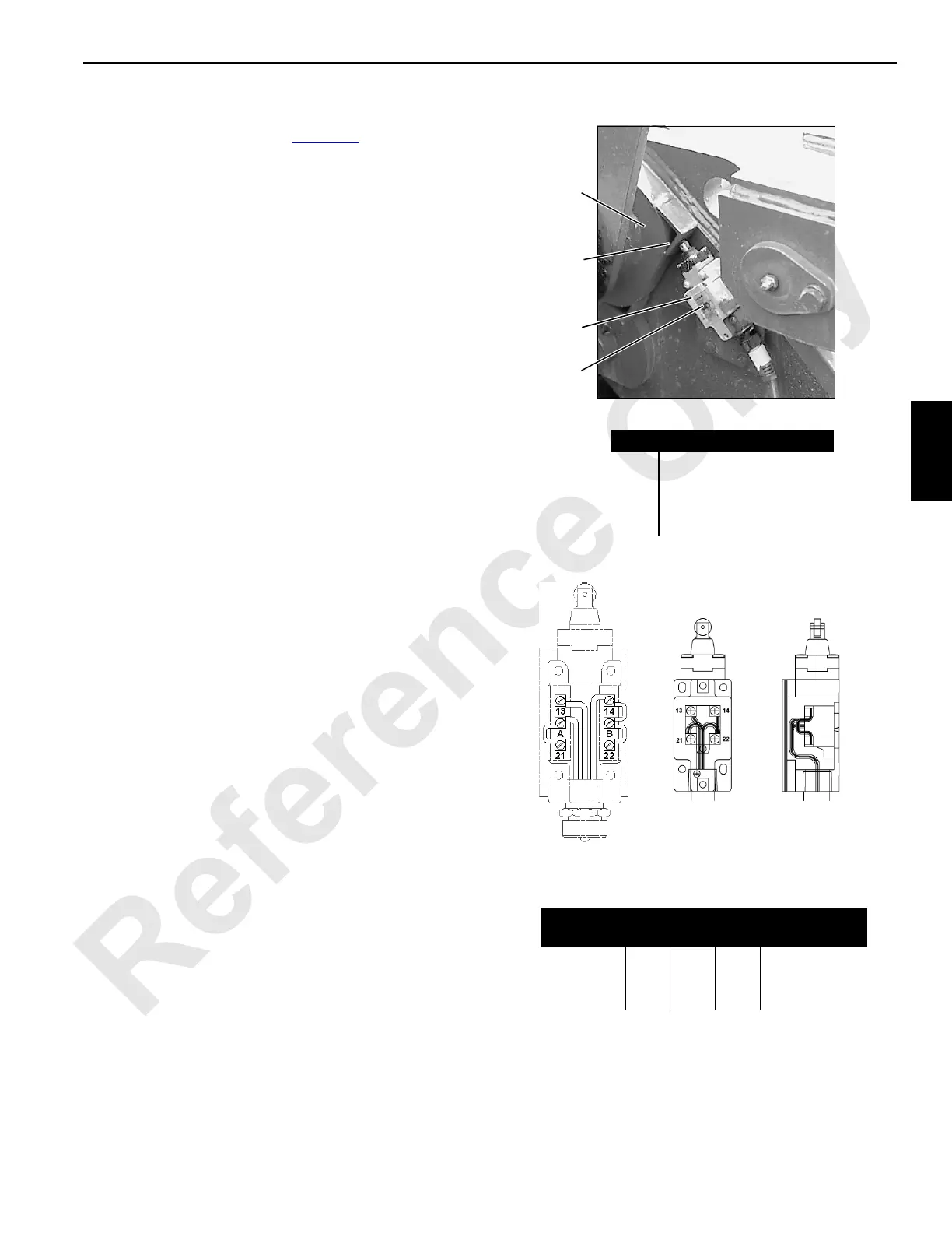
GANTRY LIMIT SWITCH
The gantry has a limit switch (3, Figure 4-6) which provides a
digital input to the crane’s programmable control for mast
raising operation.
NOTE: Reference to LED is past production only.
Operation
When gantry (1) is less than fully raised, limit switch (3) is
open and LED (4) is off.
When gantry is fully raised, actuator (2) closes limit switch
(3) and LED (4) switches on.
Check limit switch for proper operation each time crane is
assembled.
Adjustment
The gantry limit switch was set at the factory and should not
require periodic adjustment. Adjustment is required if parts
are replaced.
1. Park the crane on a firm level surface or level the crane
by blocking under crawlers.
2. Fully raise the gantry (see Mast Raising Procedure in
Section 4 of Operator Manual).
3. Loosen screws securing limit switch (3) to frame.
4. Slide limit switch down until LED is off.
5. Slide limit switch up against actuator (2) until switch
“clicks” closed and LED (4) is ON.
6. Hold limit switch in place and tighten mounting screws.
7. Test limit switch for proper operation by lowering and
then raising gantry.
FIGURE 4-6
Item Description
1 Right Gantry Leg
2Actuator
3 Limit Switch
4 LED (light-emitting diode)
1
2
3
Limit Switch Wiring
Receptacle
Switch
Terminals
Function
1 (green) 22
B14
Max Angle
2 (black) 21
A
LED
3 (white) 13 24 VDC Supply
4
P318
14CSM4-6
M100004
Past Production
Current
Production

 Loading...


