Manitowoc Published 09-10-14, Control # 065-24 1-35
14000 SERVICE MANUAL INTRODUCTION
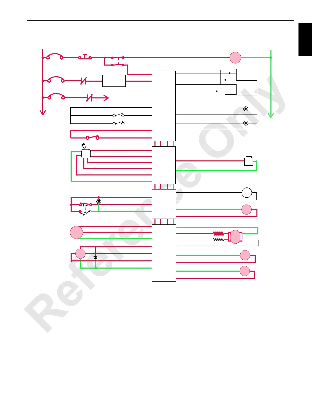
Lowering Boom
When drum 4 control handle is moved forward for booming
down, an input voltage of 2.6 volts or more is sent to node 1
controller. Node 4 controller sends a variable 0 to 24 volt
output that is divided by resistors and applied to pump EDC.
Node 4 controller also sends a variable 0 to 24 volt output
that is applied to motor PCP. Node 1 controller checks that
boom up limit switch is closed and that no system fault is
present.
Pump EDC tilts swashplate in up direction to satisfy pressure
memory. Node 1 controller compares drum holding pressure
to value in pressure memory. When system pressure is high
enough, node 4 controller sends a 24 volt output to brake
release solenoid HS-11. Brake solenoid shifts to block drain
port and opens port to low-pressure side of system to
release drum 4 brake.
When brake is released, pump EDC tilts swashplate to
stroke pump in down direction. In down direction, hydraulic
Jib Up Limit Bypass
Limit Bypass
Display 1
Display 2
WCP
P12-24
RCL Caution
RCL Warning
P11-10
P11-29
P11-08
P11-30
DO
DO
Gnd
Gnd
+
Start
CAN Power
Run 3
Cab Power
Engine Stop
10 A
24 Volts
50 A
6C4A
6C4
CB8
6A
6C8
6C9
CB4
CB9
8C
8
NODE 0
50 A
NO
NC
AI 33-e
24 Volts 33-s
Gnd 33-N
Maximum
Boom Angle
Limit
HS
11
Lower
Raise
EDC
SS
M/C
HS
12
HS
13
FIGURE 1-20
NODE 2
NODE 4
DO P52-31
DI P51-19
DO P52-31
5 Volts P51-31
AI P51-15
34-L Gnd
44-A Gnd
44-E Gnd
44-G Gnd
44-C Gnd
24 Volts 44-n
44-B DO
34-M DO
44-F DO
44-H DO
EC2B 44-s
44-D DO
Gnd P51-22
P52-20 Gnd
P52-04 DO
Handle
Rotation
Indicator
Drum 4
Park Brake
Drum 4
Control Handle
Drum 4
Motor Control
Drum 4
Brake Release
Drum 4
Pump #4
Drum 4 Motor
Speed Sensor
Drum 4
Pawl In
Drum 4
Pawl Out
Drum 4
Pressure Sender
Hyd
Psi
Gnd 43-m
24 Volts 43-s
AI 43-r
34-a Gnd
34-b DO
NODE 3
Gnd 44-r
EC2A 44-p
–
PWR
CAB
NODE 1
(Master)
0 Volts
P12-15
P12-09
DI
DO
14CSM1-110
P11-13
P11-14
P12-01
P12-31
P12-32
P12-21
24 Volts
Gnd
CAN L
CAN H
P12-07
DI
DO
DO

 Loading...


