ELECTRIC SYSTEM 14000 SERVICE MANUAL
3-34
Published 09-10-14, Control # 065-24
Cab Tilt Status
Displays command state of cab tilt cylinder —
cab up or down (shown).
Boom Hinge Pin Status
Displays command state of boom hinge pin
cylinders — extended (shown) or retracted.
Cooling Fan Status
Displays command state of cooling fan speed
status as a percentage of maximum RPM.
Engine Diagnostics Screen
Engine Prompt
Displays when continued engine operation could
result in damage to Diesel Particulate Filter (DPF).
Stop the engine when safe and call for service.
Diesel Particulate Filter (DPF) ON
Displays one of three conditions (see Engine
Manufacturer’s manual for additional
information):
• DPF is starting to fill. Ensure Regeneration Inhibit Switch
is OFF. No immediate action is required. Perform a
Stationary Regeneration at earliest convenience.
• Diesel Particulate Filter (DPF) FLASHING — DPF is
nearly full. The operator may sense a reduction in
power. Ensure Regeneration Inhibit Switch is OFF. No
immediate action is required, but a Stationary
Regeneration should be initiated as soon as possible.
• Diesel Particulate Filter (DPF) FLASHING and Check
Engine light ON. The DPF is full. The operator will notice
that engine power is significantly reduced. Stop
operation and perform a Stationary Regeneration
immediately.
DPF Regeneration Inhibited
Displays when active regeneration has been
disallowed by pressing the Regeneration Inhibit
switch. Excessive use of Regeneration Inhibit will
result in the need to service or replace the DPF.
High Exhaust System Temperature
(HEST)
Displays when higher than normal exhaust
temperatures may exist due to DPF regeneration.
See Engine Manufacturer’s manuals for additional
information.
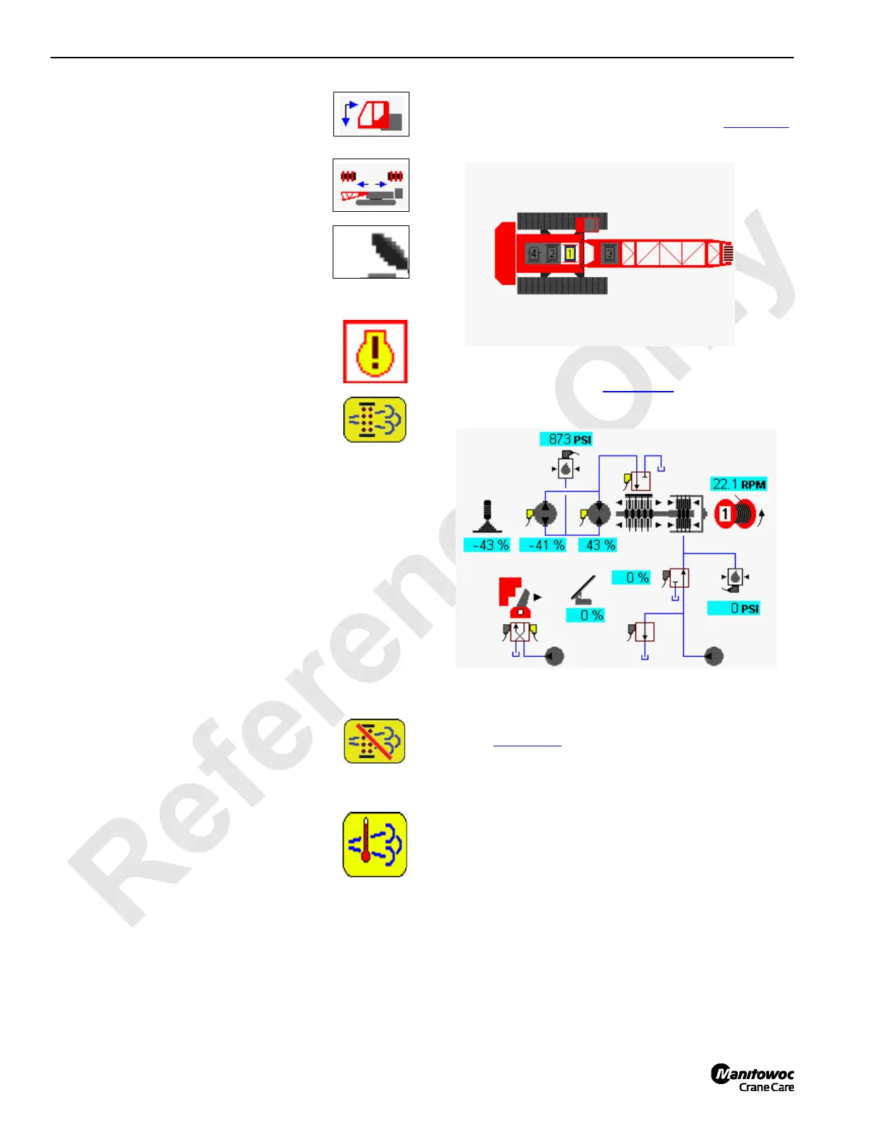
Drum Diagnostic Screens
Select drum icon in screen level 1 as shown Figure 3-9.
Press Enter button to go to level 2.
In drum example shown in Figure 3-10
, drum 1 function is
shown lowering. Load drum 2 operation is similar.
For load drum 3, left travel pump is dedicated to operate
drum 3 motor through diverting valve when drum 3 is
selected (Figure 3-11
). Drum 3 is inoperable when traveling.
Drum 3 can be configured as a load drum or luffing jib.
FIGURE 3-9
Diagnostic Screen
Drum 1 Selected
14COM3-31
FIGURE 3-10
Drum 1
14COM3-32

 Loading...


