INTRODUCTION 14000 SERVICE MANUAL
1-44
Published 09-10-14, Control # 065-24
DRUM 1 AND DRUM 2 - FREE FALL
(OPTIONAL)
See Figure 1-26, Figure 1-27, and Figure 1-28 for the
following procedure.
The front drum, rear drum or both drums can be equipped
with free fall option. In free fall, the left clutch/brake pedal
operates the front drum while right clutch/brake pedal
operates the rear drum when lowering the load. When
hoisting in free fall, the drum control handles operate the
same as in normal operation. See Drum 1 and Drum 2
System topics for a description of front and rear drum
operation.
An engine driven hydraulic gear pump supplies hydraulic
fluid at 3,000 psi (207 bar) to operate front/rear drum free fall
systems.
Hydraulic fluid flows free fall enable solenoid valve to tank
when free fall is not active. System pressure is not high
enough to release spring-applied clutch/brakes. A pressure
sender for each free fall drum in manifold provides system
pressure information to node-1 controller.
Front or rear drum pump and motor case drains are
connected together and routed to system drum clutch/brake
housing. Case drain cooling fluid enters the center of clutch/
brake housing and exits at top of housing. From clutch/brake
housing outlet the cooling fluid returns to tank.
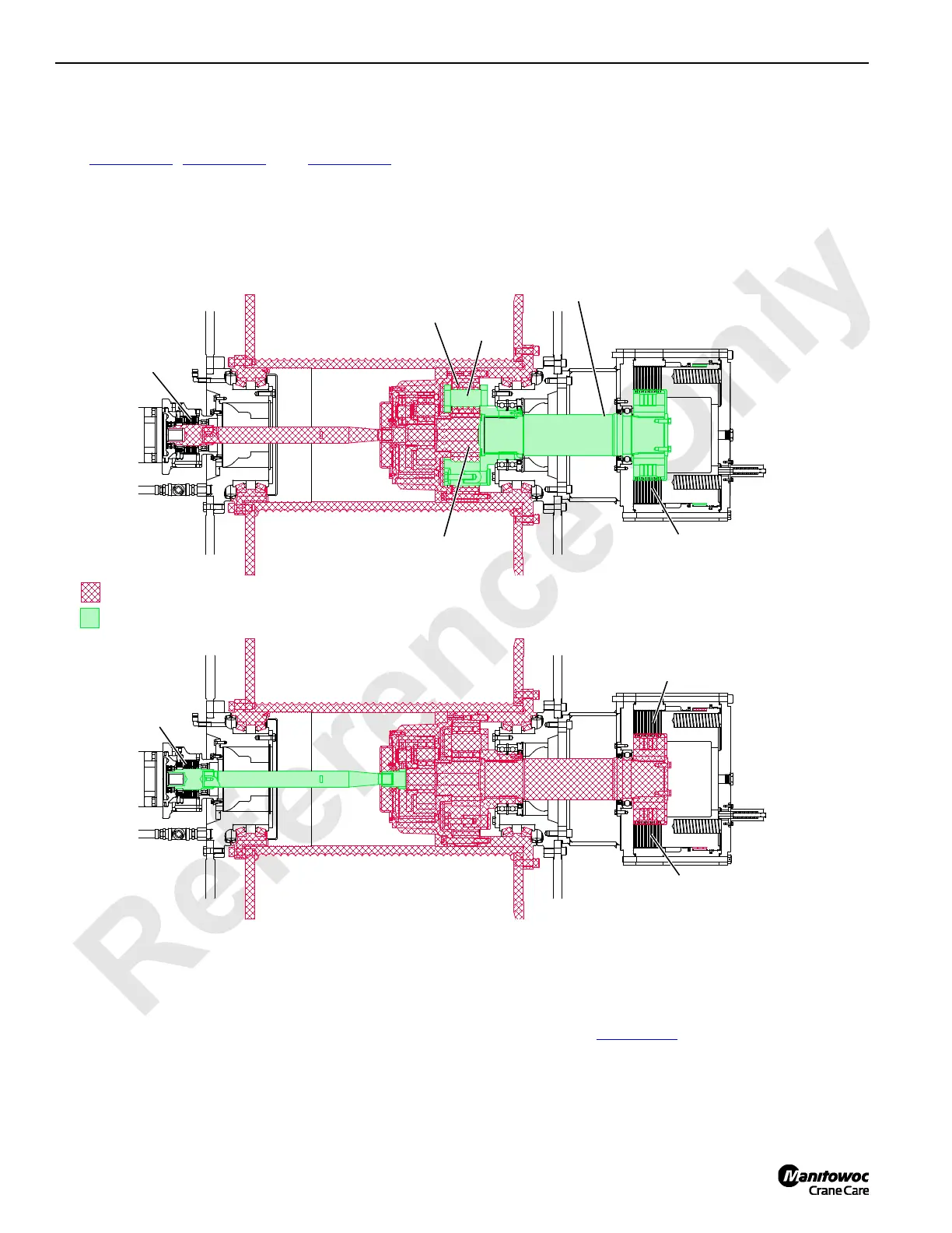
When clutch/brake is applied, the shaft is engaged with drum
planetary gears (Figure 1-26
). In full power, the drum is
powered from the motor shaft through planetary gears to
rotate the drum. The free fall clutch/brake shaft is attached to
the third planet gear carrier and does not rotate when
operating in full power.
DRUM BRAKE
ENGAGED
FIGURE 1-26
Free Fall Operation
Free Fall
Clutch Shaft
RG-16
Rotating Components
Sun Gear
Stationary Components
RG-17
Full Power Operation
Friction Discs Rotate
Planetary
Carrier
Friction Discs and Outer
Plates Stationary
Free Fall Clutch/Brake
Engaged
Drum Brake
Released
Free Fall Clutch/Brake
Disengaged

 Loading...


