Manitowoc Published 09-10-14, Control # 065-24 3-33
14000 SERVICE MANUAL ELECTRIC SYSTEM
Diagnostic Screens
Diagnostic screens show a graphic of hydraulic circuit and
status of all pumps, motors, valves, and switches that apply
to crane function selected.
This view-only screen operates on two levels:
Level 1— Image of electrical tester shown (see Figure 3-7
).
Use Select buttons to highlight individual crane functions.
Level 2 — Shows Diagnostic screen for highlighted crane
functions.
The yellow alert symbol is displayed if a system fault occurs.
You must go back to Information screen to identify the fault.
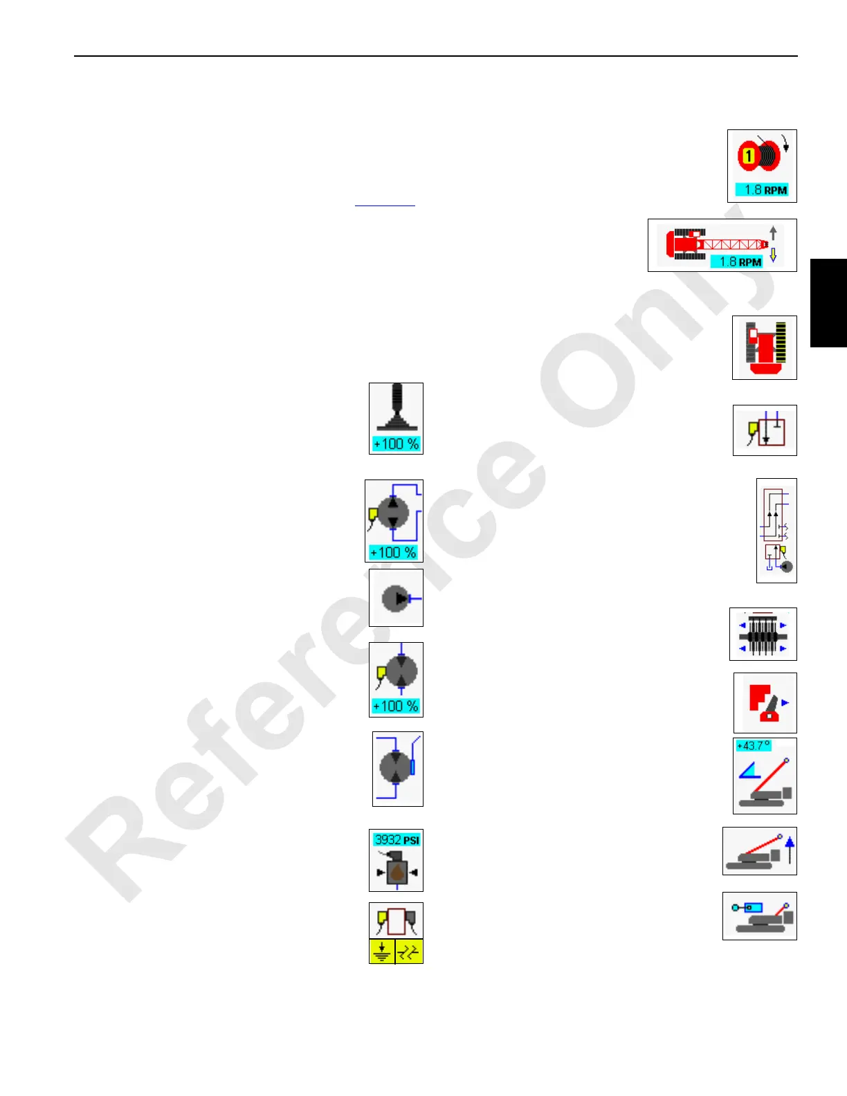
Diagnostic Screen Component Icons
Each Diagnostic screen component icon is identified and
described in the following paragraphs.
Control Handle
Displays system control handle command in
percent from neutral with +raise and –lower for
drums, +right and –left for swing, and +forward
and –reverse for travel.
Variable Closed-Loop Pump
Pump command from neutral (0%) to +/-% of full
displacement for drums, swing, and travel.
Gear Pump
Accessory pump or system charge pump
Variable Closed-Loop Motor
Displays motor command with 0% maximum
displacement and 100% minimum displacement.
Closed Loop Variable Motor with Remote
Pilot
Displays two-speed motor with remote pilot. This
motor type is used for shifting motor speeds
automatically when selected.
System Pressure Sender
Displays hydraulic pressure (psi/bar).
DIN Electrical Connector
DIN electrical connector changes to yellow when
selected item is enabled. The yellow short to
ground icon or open circuit icon indicates a circuit
fault that must be serviced immediately.
NOTE: Variable outputs may show a yellow icon at all
times.
Drum Speed
Displays drum speed in revolutions per minute
(RPM). Drum direction is also shown.
Swing Status
Displays status of swing. Swing
right (shown) or swing left arrow
is yellow when swing is enabled.
Swing speed is shown in revolutions per minute (RPM).
Track Symbol
Shows travel function. Travel (right shown) is
yellow when function is operating.
Valve Status
Displays status of a valve.
Pilot Valve
Displays status of an external piloted valve — a
diversion valve would be an example of piloted
valve.
Disc Brake
Displays disc brake status — applied or
released (shown).
Drum Pawl
Displays pawl status — engaged or disengaged
(shown).
Mast Angle
Displays mast angle in degrees the mast is
positioned above transport position.
Mast Raise Status
Displays command state of mast raise
cylinders.
Gantry Down Limit Status
Displays command state of gantry movement
and gantry down limit switch— open or closed
(shown).

 Loading...


