ELECTRIC SYSTEM 14000 SERVICE MANUAL
3-2
Published 09-10-14, Control # 065-24
CIRCUIT BREAKERS
Engine Node
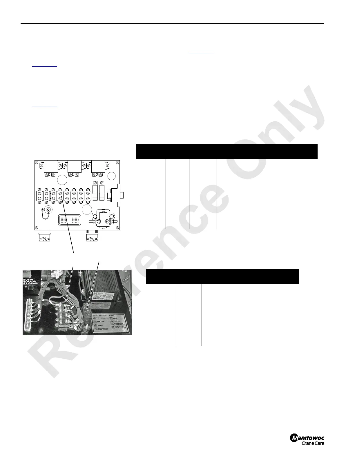
See Figure 3-1 for the following procedure.
Circuit breakers CB-1 through CB-9 are mounted in engine
node 0 controller box in left side enclosure.
Operator’s Cab
See Figure 3-1 for the following procedure.
Circuit breakers CB1 through CB4 and fuses F1 through F4
are mounted in rear console behind operator’s seat.
Grid Heater
See Figure 3-2 for the following procedure.
One 120 amp circuit breaker and one high power relay
contactor is located in the grid heater Junction Box mounted
in the engine compartment. Access to circuit breaker and
relay is through hinged junction box front cover. The cover is
held in place by three mounting brackets and screws.
MS1
CB7CB6CB5CB4CB3 CB8CB2
P1
CB1
10A
8A
10A 15A 30A 30A 50A
CB9
50A
CAN
BUS
POWER
CAN
BUS
GROUND
CAB
POWER
FIGURE 3-1
Circuit
Breaker
Amps
Wire
No.
Description of Items Protected
CB-1 60 6A Main System 24 Volt Power
CB-2 8 6C2 ECM Key Switch (Cummins)
CB-3 10 6C3 Cummins Diagnostics
CB-4 10 6C4 Key Switch (Cummins)
CB-5 15 6C5 Air Compressor Clutch
CB-6 30 6C6 Cummins ECM
CB-7 30 6C7 Starter Solenoid
CB-8 50 6C8 CAN-Bus Power
CB-9 50 6C9 Cab Power
Circuit
Breaker
Amps Description of Items Protected
CB1 25 DC Converter
CB2 25 Air Conditioning/Heater Fan
CB3 15 Front and Overhead Wiper
CB4 15 Back Lighting / Work Lights
F1 10 Radio
F2 10 Boom RIN
F3 10 Power Point (Left Console)
F4 10 Power Point (Right Console)
P2432
Rear Console at Back of Cab
Circuit
Breakers
Fuses
A16276
Right Side Enclosure

 Loading...


