BOOM 14000 SERVICE MANUAL
4-6
Published 09-10-14, Control # 065-24
BOOM AND LUFFING JIB ANGLE
INDICATOR CALIBRATION
An angle indicator potentiometer is located inside the node
controller mounted on the boom top and the luffing jib top.
Boom and luffing jib angles are calibrated automatically by
the crane’s programmable controller as part of load indicator
calibration procedure (see Rated Capacity Indicator/Limiter
Operation Manual for instructions).
MAST ANGLE ADJUSTMENT
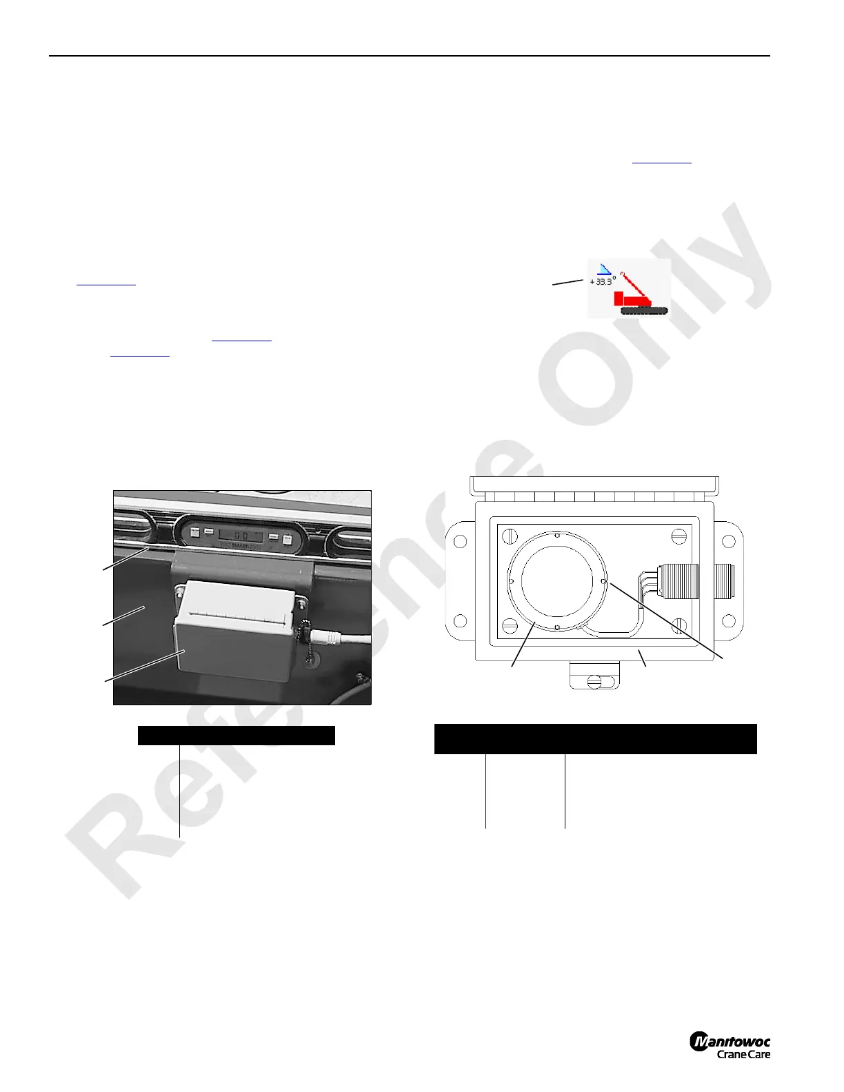
See Figure 4-4 for the following procedure.
Mast Angle Sensor
Mast angle sending unit (3, Figure 4-4) houses a solid-state
sensor (4, Figure 4-5
) which provides an electric signal to the
crane’s programmable controller. The programmable
controller uses the signal for the following purposes:
• Automatically control the position of mast raising
cylinder and levers during crane setup
• Allow operator to monitor mast angle on the display
during crane setup
Adjusting Mast Angle
The mast angle sensor was set at the factory and should not
require periodic adjustment. Adjustment is required if parts
are replaced.
1. Park the crane on a firm level surface or level the crane
by blocking under crawlers.
2. Lower the mast (2) to transport position.
3. Place digital protractor-level (1, Figure 4-4
) on the mast
and note mast angle.
4. Go to MAST ANGLE on information screen of main
display. Note mast angle.
5. Angle noted in steps 3 and 4 must match within 1°.
6. If necessary, loosen mounting screws and rotate
sending unit (3) in mounting slots until reading on
display matches angle on level.
7. Securely tighten mounting screws to lock adjustment.
FIGURE 4-4
Item Description
1 Digital Protractor-Level
2 Left Mast Leg
3 Angle Sending Unit
4 Mast Angle Sensor
5 Scribe Line
1
2
3
P317
FIGURE 4-5
Wires
Receptacle
ID
Function
Red J1-A Supply Voltage — 5 VDC or 10 VDC
Green J1-B Analog Output 1 — 0 to 5 VDC
Black J1-C System Ground Power and Signal
White J1-D Analog Output 2 —0 to 10 VDC
4
5
3
A11126

 Loading...


