ELECTRIC SYSTEM 14000 SERVICE MANUAL
3-28
Published 09-10-14, Control # 065-24
levels show icons and/or data boxes that can be selected to
change parameters and/or to enter different screen levels.
Screen Prompts
Screen prompts can appear on a selected screen if a fault
condition exists or to prompt or confirm certain operator
actions when required by the system. Prompt descriptions
and icons are shown below.
• Rated Capacity Indicator/Limiter Display
is item 1 and the Main Display is item 2
• Yellow alert symbol is displayed if a system fault
occurs. See Information screen topic in this
section to access faults.
• Engine alert symbol is displayed when the
engine needs to be serviced at the first available
opportunity (water-in-fuel detected or coolant
level low). Also appears when DPF alert is on
indicating DPF is nearly full or full and a stationary
regeneration is required.
• Purple confirm prompt appears when the
operator shall start certain test routines from the
screen and to confirm data when required.
• Engine stopped symbol is displayed when the
engine is stopped.
• Remote control symbol is displayed when
remote control operation is selected.
The Manitowoc screen displays the following
program items (see Figure 3-6
):
• Model/Program Number (14000 FCN number
shown)
• Con Number (009 000 000 008 shown)
• Screen Program Number (GUI 2.007 shown)
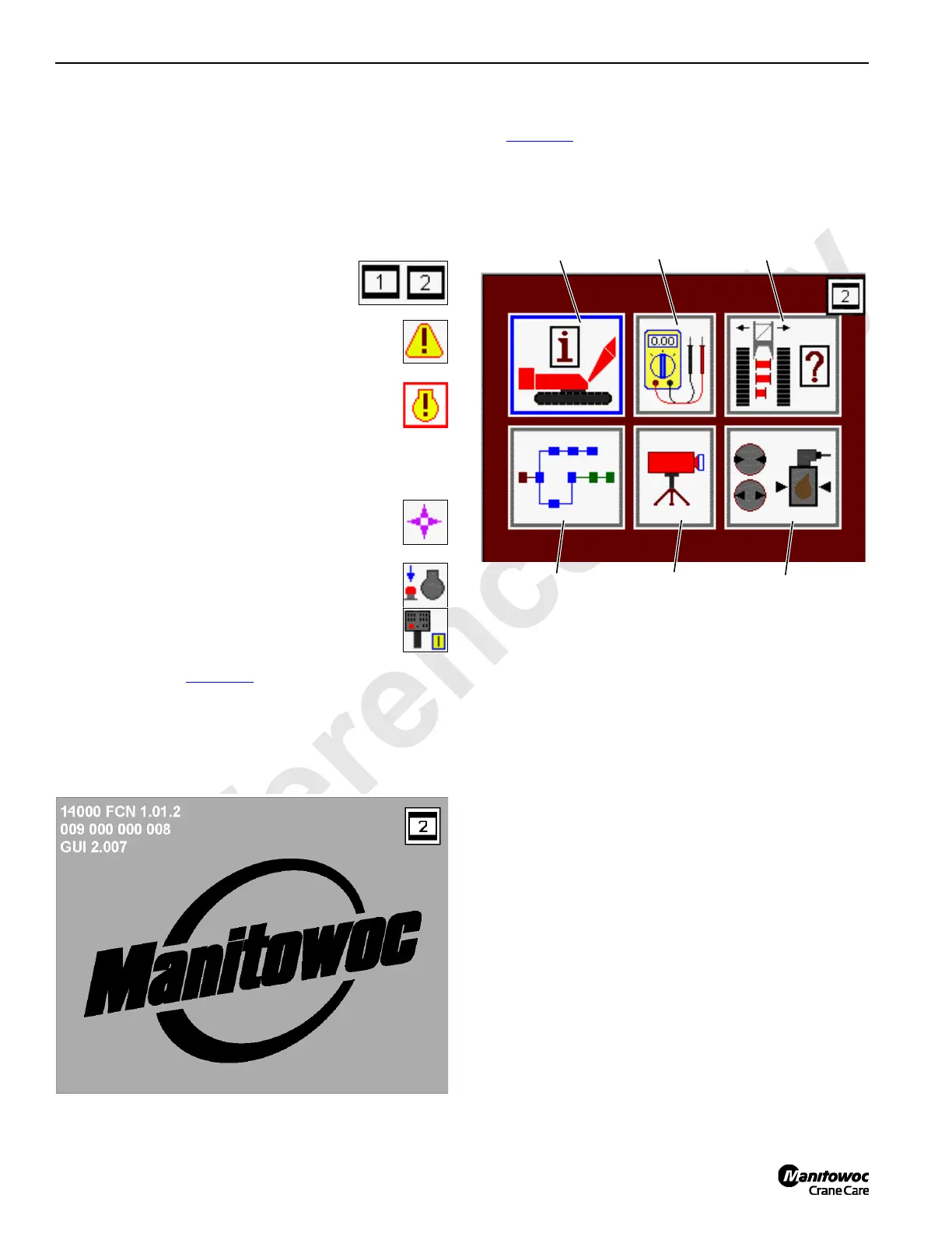
Menu Screen
See Figure 3-7 for the following procedure.
The Menu screen is the base screen for the crane system.
All other screens must be entered from this screen. Exiting
from any screen will return to the Menu screen.
The Menu screen shows six screen icons:
1. Information Screen icon
2. Diagnostic Screen icon
3. Function Mode Screen icon
4. CAN Bus Screen icon
5. Camera Screen icon
6. Pressure Test and Calibration Screen icon
The Menu screen operates on one level only.
• Use Select buttons to highlight icon that represents
the screen to be entered. Press the Enter button to
go to selected screen.
• To return to Menu screen, press Exit button until
Menu screen appears.
FIGURE 3-7
CAN Bus
Screen
Diagnostic
Screen
Camera
Screen
Function Mode
Screen
Pressure Test and
Calibration Screen
14COM3-27-2
Information
Screen

 Loading...


