Manitowoc Published 09-10-14, Control # 065-24 2-27
14000 SERVICE MANUAL HYDRAULIC SYSTEM
5. Loosen lock nut (2).
6. Using an internal hex wrench, turn adjusting screw (3) in
until pressure increases in either gauge.
7. Note angular position of internal hex wrench.
8. Then, turn adjusting screw out until pressure increases
an equal amount in other gauge.
9. Again, note angular position of internal hex wrench.
10. Turn adjusting screw in half the distance between
positions noted above.
11. Pump control should now be in neutral with both gauges
reading same pressure.
12. Hold adjusting screw (3) in position and securely tighten
lock nut (2).
13. Stop the engine, remove gauges, and securely install
servo gauge port plugs (1).
Motor Leakage Test
Perform the following test if troubleshooting indicates the
need:
• Low Charge Pressure
• Sluggish Operation
• Excessive Heat
See Figure 2-28
for the following procedure.
1. Stop the engine.
2. Install an accurate flow meter in highest case drain port
(see Figure 2-13
) at desired motor.
• A 3,000 psi (207 bar) in-line meter with a flow rate of
30 gpm (114 L/m) is required.
• All motors except swing require 16 ORS fittings.
Swing requires 12 ORS fittings.
3. For hoist motors only, disable loop flushing as follows:
a. Disconnect loop flushing hose (2) from elbow in loop
flushing valve (1).
b. Install an 08 ORS cap on end of elbow and an 08
ORS plug in end of hose.
4. Start and run the engine at high idle.
5. Monitor flow meter. Under all operating conditions,
leakage should not be more than 1-1/2 to 2-1/2 gpm (5.7
to 9,5 L/m.
6. Stop the engine and enable loop flushing by
reconnecting hose to elbow in loop flushing valve.
7. Start and run the engine at high idle.
1
2
Item Description
1 Servo Gauge Ports (SAE 06)
2 Lock Nut
3 Adjusting Screw
Wrench Size
Pump Series
Lock Nut
Hex Size
Internal
Hex Size
Early Series Units 17 mm 5 mm
Current Series Units 10 mm 3 mm
FIGURE 2-27
P1535a
Typical Pump Installation
3
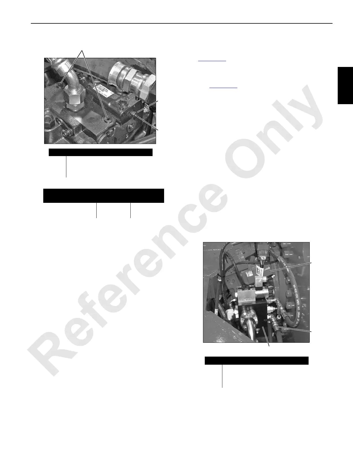
FIGURE 2-28
Typical Motor Installation
Item Description
1 Loop Flushing Valve
2 Loop Flushing Hose
3 Motor
1
2
3
P2297b

 Loading...


