Manitowoc Published 09-10-14, Control # 065-24 3-35
14000 SERVICE MANUAL ELECTRIC SYSTEM
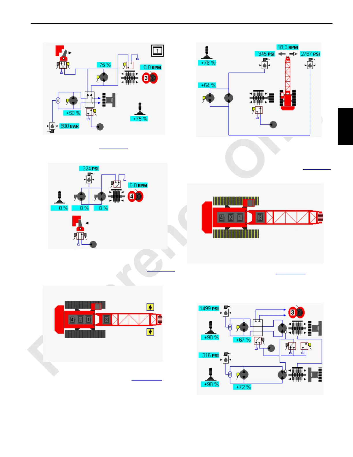
In drum example shown in Figure 3-12, drum 4 function is
shown not operating.
Swing Diagnostic Screen
Select swing icon in screen level 1 as shown in Figure 3-13.
Press Enter button to go to level 2.
Swing system icons are displayed in Figure 3-14
. The
example shows how swing function might appear when
swinging right. Arrow symbols near each pressure sender
indicate which sender monitors swing right and swing left
pressures.
Travel Diagnostic Screen
Select travel icon in screen level 1 as shown in Figure 3-15.
Press Enter button to go to level 2.
In travel system example shown in Figure 3-16
, left travel
pump is dedicated to operate drum 3 through diverting valve
if drum 3 is selected. When left crane travel is enabled, drum
3 is disabled.
FIGURE 3-11
Drum 3
14COM3-33
FIGURE 3-12
Drum 4
14COM3-34
FIGURE 3-13
14COM3-35
Swing Diagnostic
Screen Selected
FIGURE 3-14
14COM3-36
Swing Right
Selected
14COM3-37
Travel Diagnostic
Screen Selected
FIGURE 3-15
FIGURE 3-16
14COM3-38
Travel Forward Selected

 Loading...


