INTRODUCTION 14000 SERVICE MANUAL
1-50
Published 09-10-14, Control # 065-24
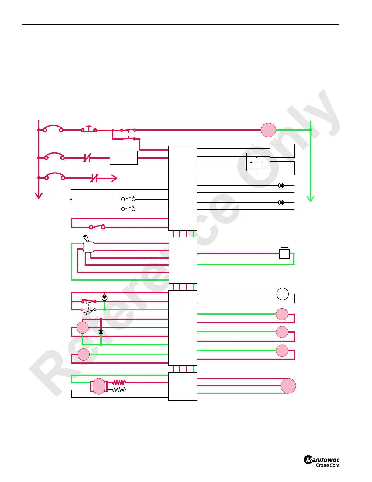
When drum 3 control handle is moved to toward neutral
position, node 1 controller compensates for hydraulic system
leakage or changing engine speed. This shifts the motor
back to maximum displacement for slower output speed to
slow drum rotation.
When control handle is moved to neutral position, node 4
controller sends a zero output voltage to pump EDC that
moves swashplate to center position. Node 1 controller
stores the load holding pressure in pressure memory. After
drum 3 control handle center switch opens, node 3 controller
sends a zero output voltage to disable drum brake release
solenoid HS-7. Drum brake solenoid valve shifts to block
pilot pressure to brake and opens a line to tank. Brake
applies before drum pump de-strokes.
Drum 3/left travel to diverting solenoid HS-10 remains
enabled until left travel handle is moved.
HS
9
HS
8
34-J Gnd
34-R DO
Drum 3
Pawl In
Drum 3
Pawl Out
34-X Gnd
34-Z DO
Jib Up Limit Bypass
Limit Bypass
Display 1
Display 2
WCP
P12-24
RCL Caution
RCL Warning
P11-10
P11-29
P11-08
P11-30
DO
DO
Gnd
Gnd
+
Start
CAN Power
Run 3
Cab Power
Engine Stop
10 A
24 Volts
50 A
6C4A
6C4
CB8
6A
6C8
6C9
CB4
CB9
8C
8
NODE 0
50 A
Drum 3/ Left
Travel
Diverting
HS
10
Gnd 34-G
DO 34-H
Hyd
Psi
46-U Gnd
46-T 24 Volts
46-e AI
EDC
Gnd 44-L
Gnd 44-K
DO 44-M
DO 44-S
Drum 3/ Left
Travel Pump
#3
NO
NC
HS
7
M/C
FIGURE 1-29
Drum 3
Park Brake
NODE 2
NODE 3
NODE 4
Gnd 33-E
DI P12-15
DO P12-08
DO P52-10
DI P51-09
DO P52-10
5 Volts P52-35
AI P51-05
Gnd P51-22
24 Volts 33-V
AI 33-c
34-d DO
P52-23 Gnd
P52-03 DO
34-c Gnd
34-e Gnd
34-f DO
Drum 3
Control Handle
Drum 3
Minimum Bail
Limit
Handle
Rotation
Indicator
Drum 3
Motor Control
Drum 3
Brake
SS
24 Volts 34-n
EC3B 34-s
Drum 3 Motor
Speed Sensor
Gnd 34-r
EC3A 34-p
Raise
Lower
–
PWR
CAB
NODE 1
(Master)
0 Volts
Drum 3/
Left Travel
Pressure
Sender
14CSM-1-116
P11-13
P11-14
P12-01
P12-31
P12-32
P12-21
24 Volts
Gnd
CAN L
CAN H
P12-07
DO
DO
DI

 Loading...


