12-4 Probes and Biopsy
<4> Transducer connector
Used to connect the transducer to the ultrasonic diagnostic
system.
<5> Lock handle
This locks the connector to the ultrasonic diagnostic
system.
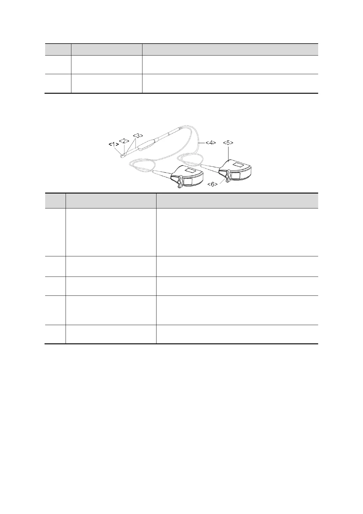
The probes’ structure marked <2> in the figure above may vary with the matched needle-
guided brackets.
Probe 65EB10EA
No. Name Function
<1>
<2>
<1>Transducer head
(convex, vertical section)
<2>Transducer head
(convex, horizontal section)
It utilizes the piezoelectric effect to convert electrical
signals into ultrasound waves, which are transmitted
to the body, and to generate electrical signals when
receiving the reflected ultrasound waves (echoes).The
lens on the surface is the acoustic lens. Apply
ultrasound gel on the acoustic lens.
<3> Locating groove Mount the needle-guided bracket.
<4> Cable
This transmits electrical signals between the
transducer body and connector.
<5> Connector
This connects the transducer to the ultrasonic
diagnostic system.
<6> Lock handle
This locks the connector to the ultrasonic diagnostic
system.
12.1.2 Orientation of the Ultrasound Image and the
Transducer Head
The orientation of the ultrasound image and the transducer are shown below. The “MARK”
side of the ultrasound image on the monitor corresponds to the mark side of the transducer.
Check the orientation before the examination (take linear probe as an example).
 Loading...