2202MYJE-MY-C8-N_2018.02.
Chapter 5 Maintenance and Inspection
Compound 2-stage Screw Compressor 3225**C 5.5 Reassembly
5-45
5.5.6 Balance Piston Sleeve
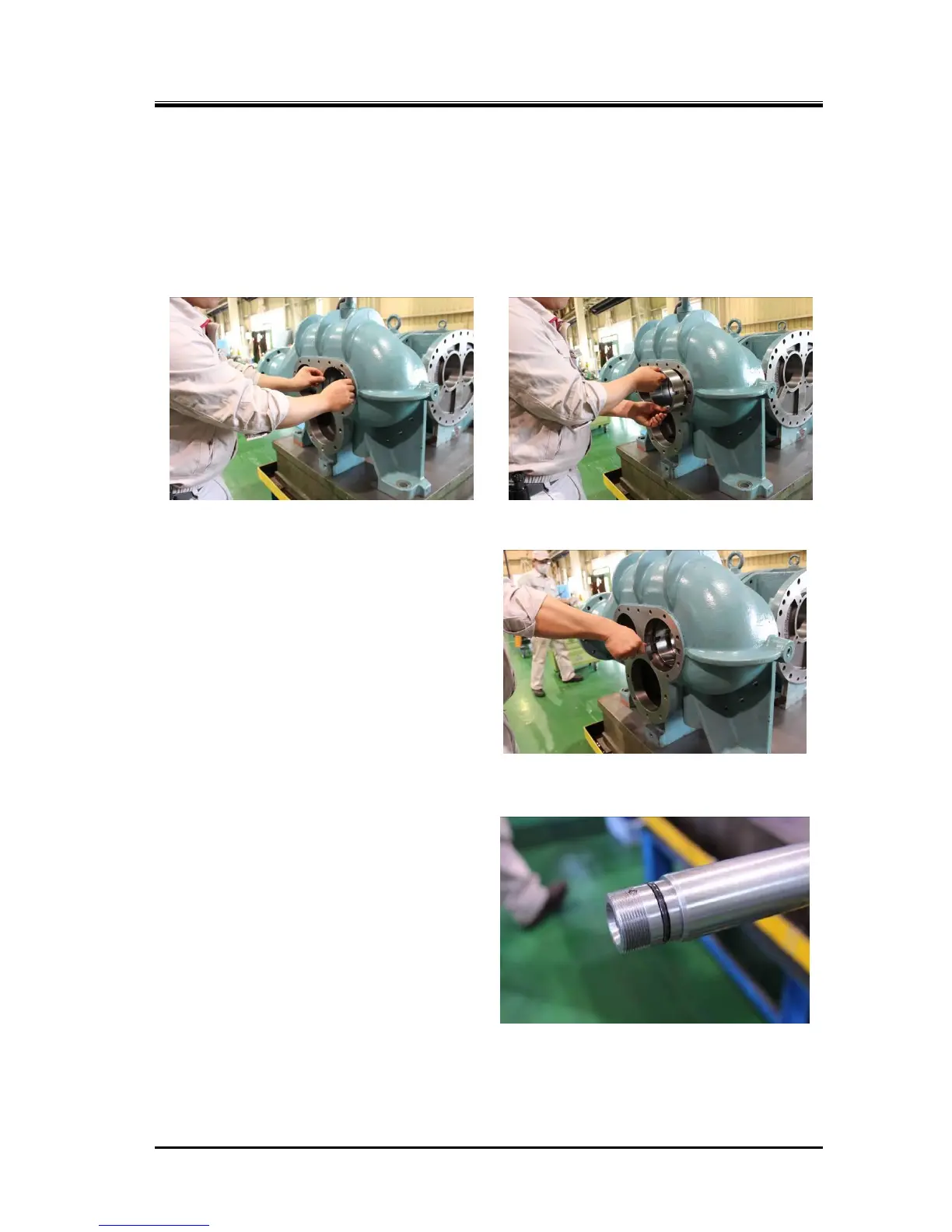
The high-stage suction cover shall be further installed with the balance piston sleeve.
a) First install the snap ring for the O-ring retainer [37], and then install the spacer [36].
b) After setting the O-ring [35] in position, install the balance piston sleeve [33].
Insert the chamfered side of the balance piston sleeve towards the O-ring already placed. Also,
align the notch of the balance piston sleeve to the rotation stop/oil supply port.
Photo 066 Installing the O-ring
Photo 067 Installing the Balance Piston
Sleeve
c) Attach the set screw [34] for the balance
piston sleeve detent, and attach a remaining
set screw from the opposite side (F rotor side)
to secure the set screw which is attached
earlier.
d) Insert the snap ring [37] to retain the balance
piston sleeve. As it should be difficult to fit the
snap ring into the groove due to the elastic
force of the O-ring, either push the side of the
ring by a guide bar or tap the head of the
guide bar to fit the ring securely into the
groove.
e) Install the O-ring [73] on the unloader push
rod (Photo 069).
Photo 068 The Balance Piston Sleeve Detent

 Loading...