5.5.3 Bearing Head and Main Rotor Casing
Since the bearing head gasket [12] is not symmetrically shaped, carefully check the
orientation when installing the gasket.
If you place the bearing head gasket by just hanging it on the stud bolts, the gasket
will protrude into the inside of the rotor casing when the casing is assembled. Apply
sufficient amount of oil, etc. to the gasket to make it fully attached to the surface to
prevent protruding upon the assembly.
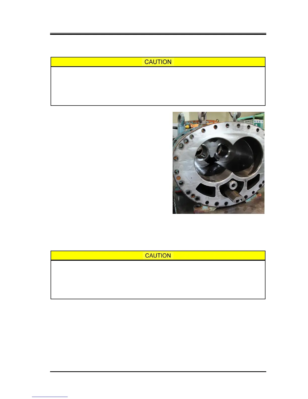
a) In case of the low-stage, after fitting the unloader
push rod [67-1] into the hole of the bearing head
[11-1], slide either the bearing head or the main
rotor casing [1-1] to mate them together.
b) Lightly fastening two bolts [2] in symmetrical position.
Next, drive in the alignment pins [3] to fix the position
by using a copper or an aluminum hammer.
c) After tightening the bolts [2], check that the bearing
head gasket is not protruding into the inside of the
casing.
d) Also, move the slide valve back and forth to check
that it works normally.
e) As the full height of the high-stage main rotor casing
is lower than that of the bearing head, both centers
will not be aligned when they are placed on the work
bench. Therefore, either use a pedestal as used in
the disassembly process or lift the rotor casing using
a crane or other device to align the centers.
The assembly procedure after mating the both
casing flanges is same as the high-stage.
f) The bottom bolts that cannot be fastened on the work
bench are to be fastened later on.
Be sure to check for possible protrusion of the gasket after the bearing head and
rotor casing have been assembled together. If you forget to check it out, it may lead
to a measurement error in the end clearance adjustment process, as the gasket may
be placed in between the rotor end and the bearing head surface. Furthermore, if the
compressor is operated after the end clearance is erroneously adjusted and fixed in
this condition, it may compromise the performance.

 Loading...