2202MYJE-MY-C8-N_2018.02.
Chapter 2 Compressor Specifications and Structure
Compound 2-stage Screw Compressor 3225**C 2.4 Structure of Compressor
2-17
2.4 Structure of Compressor
For names and locations of each part of the compressor, refer to Section 7.1 "Exploded Views,
Assembly Sectional Views" and Section 7.2 "Parts Configuration Table" in this manual.
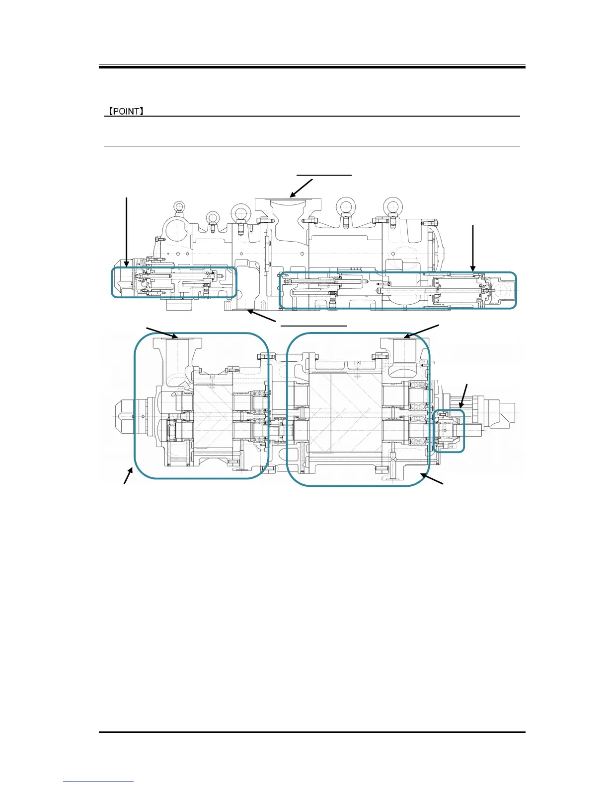
2.4.1 Sectional View
Figure 2-13 3225**C Screw Compressor Sectional Views
The 3225**C model, a compound 2-stage compressor, consists of two compressors, (i) a low-stage
compressor which suctions gas, working fluid, from the refrigerating unit and compresses (pressure-raises)
the gas and (ii) a high-stage compressor which furthermore compresses the gas that has been
pressure-raised by the low-stage compressor and sends the resulting gas to the equipment side.
In each casing (low-stage, high-stage), two screw rotors are supported on both ends by bearings. They are
meshed with each other in a joint assembly. These two screw rotors are a set of a male rotor having 4
protruding lobe profiles (M rotor) and a female rotor having 6 concave lobe profiles (F rotor). They conduct
compressing according to the mechanism explained below.
The standard compressor's M rotor is driven by a 2-pole motor; it operates at 3000 min
-1
(50 Hz) or 3600
min
-1
(60 Hz). F rotor operates at 2000 min
-1
(50 Hz) or 2400 min
-1
(60 Hz), conforming to the operation of M
rotor.
* The actual speed of a motor is less than its calculated speed (synchronous speed). This difference is
caused by slipping of the motor rotor.
The shaft of the low-stage compressor's M rotor which is linked with the motor has a shaft seal block that
keeps gas and lubricating oil from escaping from inside the compressor.
For high efficient operation, the 3225**C model has a capacity control mechanism for coping with load
change on the low-stage, and a capacity control mechanism for reducing startup load on the high-stage.

 Loading...