2202MYJE-MY-C8-N_2018.02.
Chapter 5 Maintenance and Inspection
Compound 2-stage Screw Compressor 3225**C 5.4 Disassembly and Inspection
5-36
5.4.15 High-stage Bearing Head and Main Bearings
On the rotor mounting side of the bearing head [11-2], there is a gas discharge port as determined by
the operating conditions of the compressor. This discharge port affects the performance of the
compressor.
In addition, the bearing head has the main bearing that supports one end of the rotor.
5.4.15.1 Disassembly
a) Remove all the hexagon socket head cap
screws [2-2] fastening the main rotor casing
and the bearing head. Support the foot of the
main rotor casing using squared timbers.
b) Use jacking bolts to evenly push the block.
Once some gap is produced between the
main rotor casing and the bearing head, use a
scraper to detach the gasket from the bearing
head and put it on to the main rotor casing
side.
When the alignment pins are disengaged, the
bearing head is separated from the main rotor
casing.
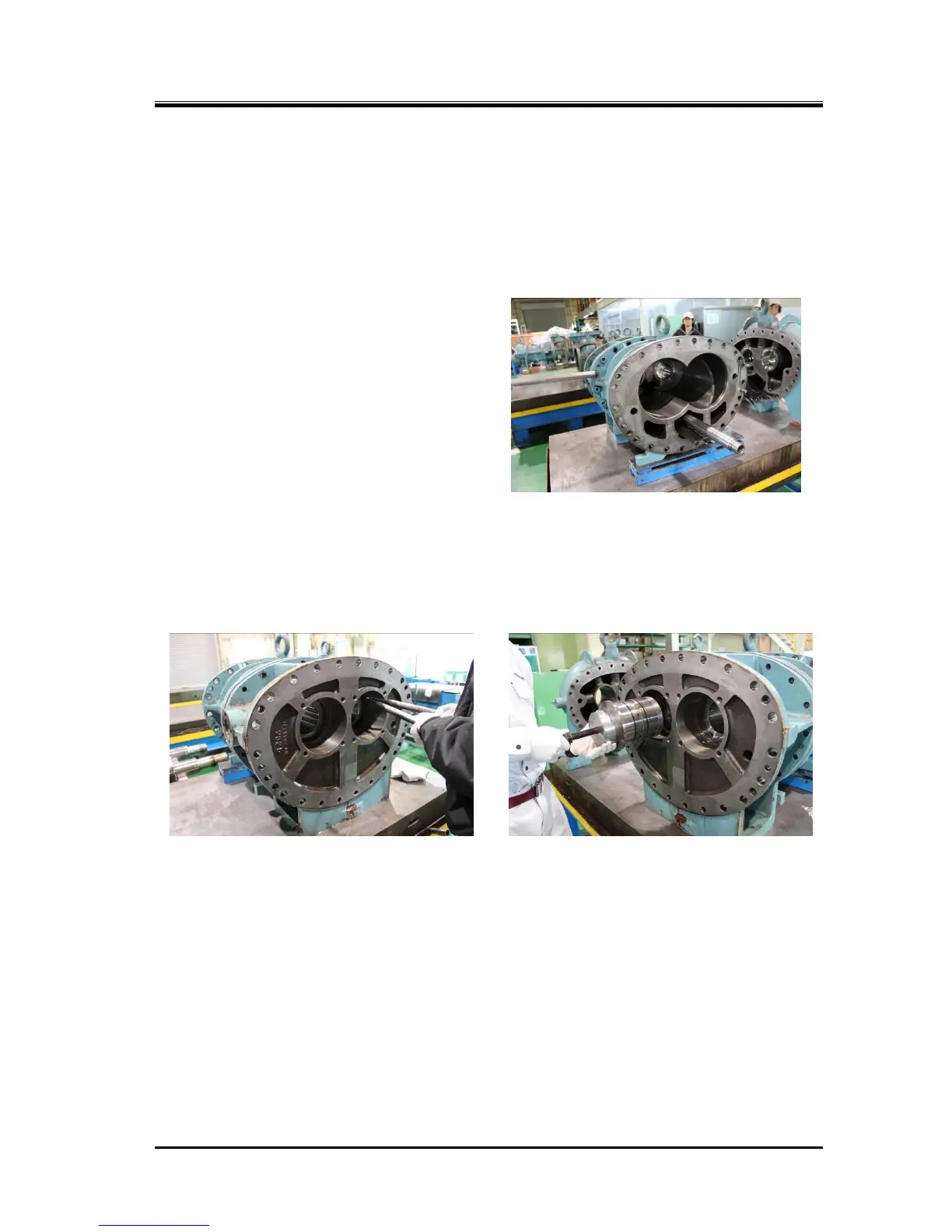
c) The main bearing [27-2] is lightly press fit into the bearing head. When removing the main bearing,
first use internal snap ring priers to remove the snap ring [29-2]. Then, either use a plastic block or
other suitable element to push the bearing from the rotor side or use a special tool such as shown in
Photo 051 to pull out the bearing. For the details of the special tool, refer to Section 5.5.2 in this
manual.
d) The unloader slide valve can be removed as an assembly by pulling it out from the bearing head
side. If no specific abnormality is found, no further disassembly is required.
e) The guide block stem [88-2] is screwed in from the bottom of the main rotor casing, and the guide
block [87-2] is engaged from the top. To replace the O-rings [89-2], remove the guide block stem.
5.4.15.2 Inspection
a) We recommend as well as the side bearings, unconditional exchange of the main bearings on the
occasion of the compressor overhaul, but for confirmation of the compressor condition and system
operating condition, carefully check the sliding part metal surface of the main bearings.
If the metal surface is gray or any foreign matter is buried, also carefully check the wear of the rotor
shaft.

 Loading...