2202MYJE-MY-C8-N_2018.02.
Chapter 5 Maintenance and Inspection
Compound 2-stage Screw Compressor 3225**C 5.4 Disassembly and Inspection
5-21
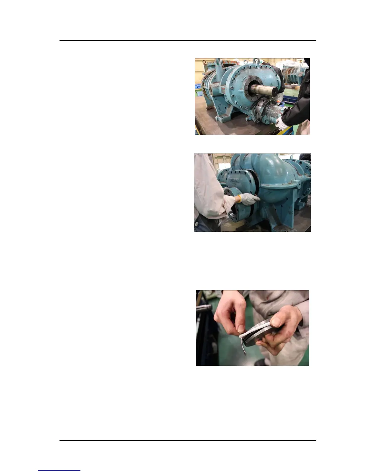
b) The low-stage unloader cylinder [60-1] is
fastened by eight long hexagon socket head
cap screws [62-1] to the low-stage bearing
head [11-1] together with the bearing cover
[16].
Even when all the hexagon socket head cap
screws are removed, the unloader cylinder will
not drop off as it is securely engaged with the
bearing cover. Pull out the unloader cylinder
by holding the flange or rib.
c) The high-stage unloader cylinder [60-2] is also
fastened by hexagon socket head cap screws
[61] (× 2) and [62-2] (× 6). The high-stage
unloader cylinder is to be pulled out similarly
to Step b) for the case of low-stage cylinder.
However, if the cylinder is to be further
disassembled, leave the two bolts [61]
fastened. Remove the bolts [24] and [62-2]
fastening the balance piston cover [22] and
remove the unloader cylinder together with
the balance piston cover. In this, as oil
remains in the balance piston and side
bearing part, be careful of the oil that will
come out when the balance piston cover is
removed. If the gasket [23] is sticking and it
does not come off, screw in two M8 eye bolts
to the two forcing screw threads on the
balance piston cover to separate the gasket.
5.4.3.2 Inspection
a) Both the O-ring [65-1] [65-2] and cap seal
[64-1] [64-2] that are on the periphery of the
unloader piston [64-1] [64-2] must be replaced
by new ones.
b) As it is often seen that the inside of the
unloader cylinder has flaws or is contaminated
by oil residue, thoroughly clean the area and
use fine sandpapers to finish the surface.

 Loading...