2202MYJE-MY-C8-N_2018.02.
Chapter 5 Maintenance and Inspection
Compound 2-stage Screw Compressor 3225**C 5.5 Reassembly
5-50
When the thrust bearing has been replaced, the dimensional difference between the
sides of the inner race and outer race varies even if it is within the tolerance of the
applicable standard specification.
As such, if the thickness of the thrust bearing alignment spacer that has been used is
insufficient, and if the lock nut is securely tightened from the first, the end clearance
between the rotor shaft end and the end face of the discharge side bearing head will
be lost. Furthermore, as the balls are pressed against the rolling contact surface to
create impression on the surface, it will damage the bearing. To avoid this, gradually
tighten the lock nut while rotating the rotor to make sure the outer race is free, until
the lock nut is fully tightened. If it comes to require more force to turn the rotor while
the lock nut is being tightened, the thickness of the spacer is considered insufficient.
5.5.8.1 End Clearance Measurement
At this point (i.e., after the thrust bearing block has been fully assembled), measure the clearance
between the bearing head end face and the rotor end face on the discharge side. This clearance is
called as the end clearance.
In particular, this measurement must be made when the thrust bearing has been replaced. Even if the
same bearing is used, the measurement should be made for verification.
If the measured clearance does not satisfy the range specified in Table 5-9, proper adjustment must be
made.
Table 5-9 Specified Range of End Clearance (unit: mm)
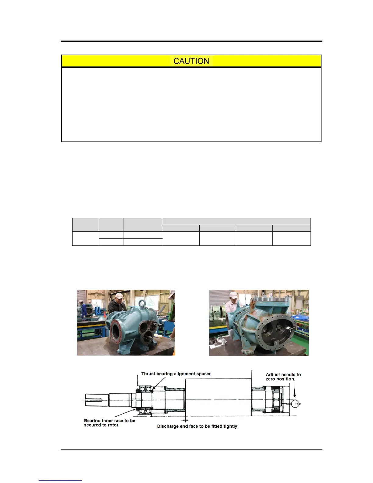
a) For pressing the rotor shaft on to the discharge side, hit the rotor shaft strongly from the suction side
while putting a jig (Teflon block).
b) Prepare the thrust bearing gland to be readily mounted. Mount a dial gauge on the suction side axial
end of the rotor, and set the indication needle to zero point while the rotor is fully pressed onto the
discharge end face (Photos 081 and 082).

 Loading...