2202MYJE-MY-C8-N_2018.02.
Chapter 5 Maintenance and Inspection
Compound 2-stage Screw Compressor 3225**C 5.5 Reassembly
5-43
5.5.4 Installing the Rotors
Note on the rotor profile of 3225**C
The rotor profile has been changed from the A profile to O profile from the production in November
1993. The biggest difference is the existence of lobe tip edge, as the A profile with lobe tip edge has
been changed to the O profile, which has no lobe tip edge.
The rotor must be sufficiently reworked. If any slight flaw is observed on the shaft surface in the area of
attaching the bearing or seal, use a sand paper to correct and finish the surface. After finishing the
surface to attach the seal, apply protective tape on the surface.
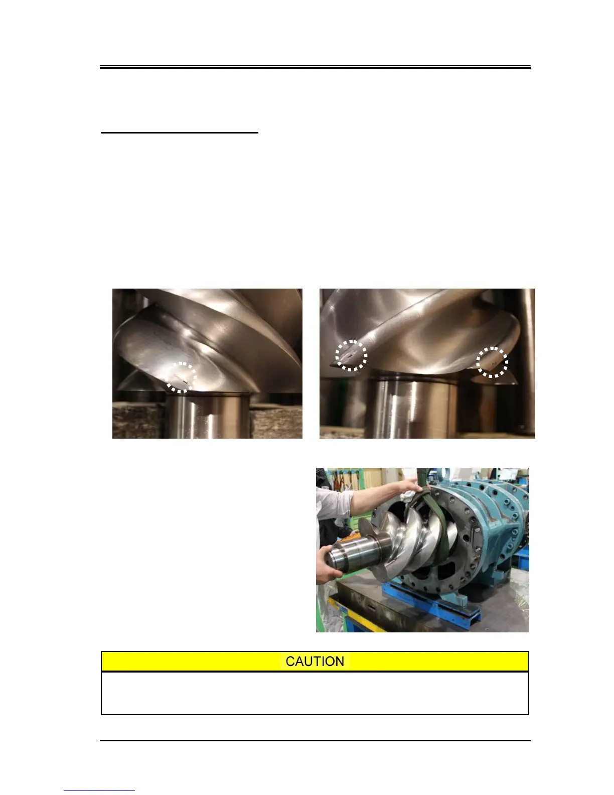
Both the M rotor and F rotor have a specific engagement position, and the position is marked by
carving.
In order to make it easier to match the positions when the rotor is installed into the main rotor casing, a
number is marked on the lobe tip: the M rotor has the marking on the discharge side, and the F rotor
has the marking on the suction side.
Photo 059 Mating Mark on the M Rotor
Photo 060 Mating Mark on the F Rotor
a) Apply sufficient amount of lubricating oil on
the main bearing in the bearing head and on
the bearing area of the rotor shaft.
b) While it is easier to mate the markings if the F
rotor is first installed into the casing, it is not a
mistake to install the M rotor first, as shown in
the photo to the right.
c) Regardless of which rotor is installed first, the
lobe of the M rotor with the carved marking of
"1" must be set in between the F rotor’s lobes
that are marked "1" and "2". As it affects
smooth engagement of the lobes as well as
the balance, be sure to mate the markings as
described above.
As the circumference of the rotor is touching the main rotor casing in this condition,
any rotation of the rotor should be kept to the minimum required. Otherwise, the
lobes tip of the rotor may be worn.
Photo 061 Installing the M Rotor

 Loading...