2202MYJE-MY-C8-N_2018.02.
Chapter 5 Maintenance and Inspection
Compound 2-stage Screw Compressor 3225**C 5.5 Reassembly
5-62
5.5.14 Coupling the High-stage and Low-stage Blocks
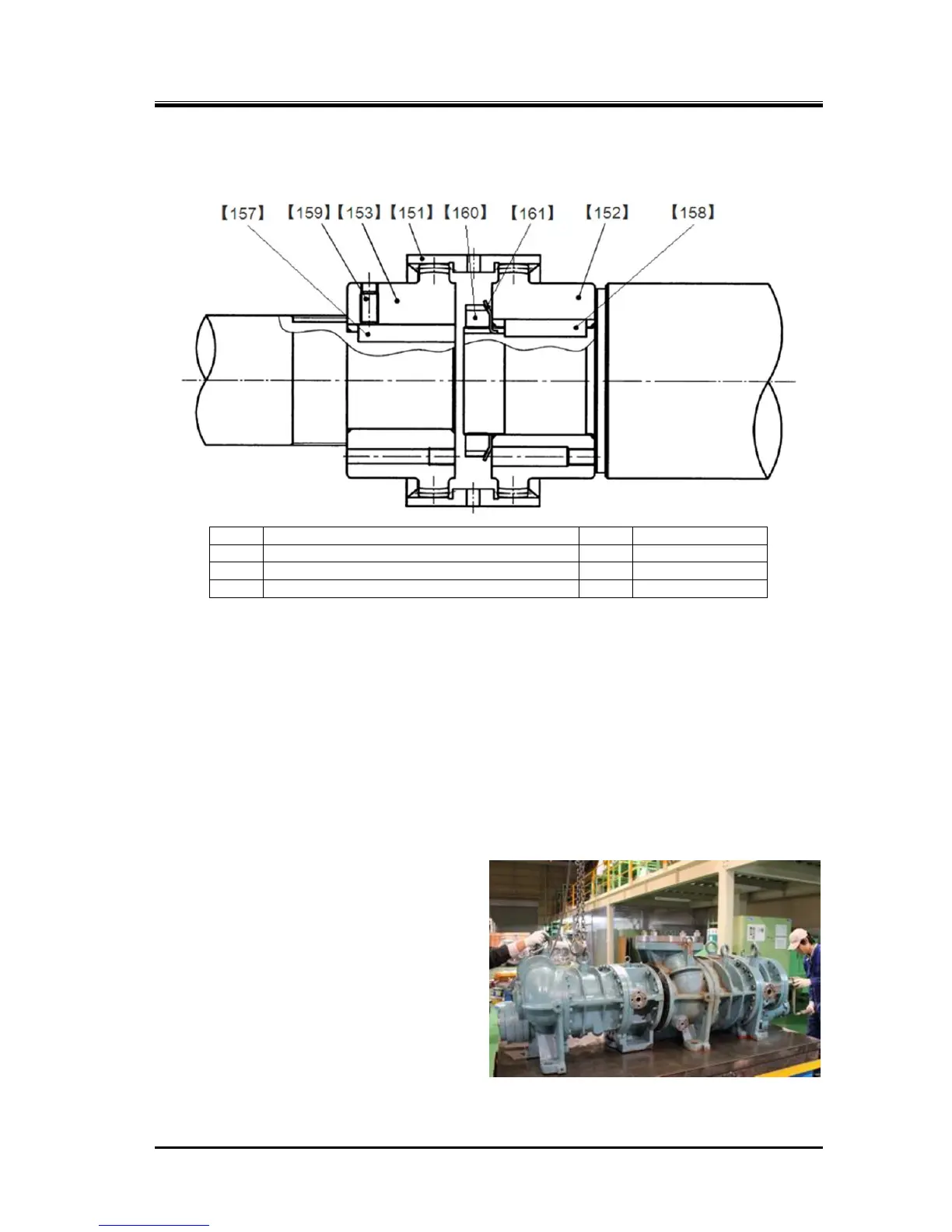
Figure 5-20 Gear Coupling Block
a) Attach the driven hub [153] of the gear coupling on the high-stage side, and fasten the M12
hexagon socket set screw [159] to hold the driven hub key [157].
This hexagon socket set screw is knurled and provided with anti-loosening.
b) On the low-stage, attach the drive hub [152], lock washer [161], and lock nut [160] in this order.
Tighten the lock nut at the specified torque or within the specified range of the tightening angle (refer
to Chapter 7, Section 7.3 "Tightening Torques for Bolts and Nuts" in this manual). Then, bend the
tooth of the lock washer at the notch of the lock nut.
c) Set the drive sleeve on the low-stage drive hub.
d) Screw in two stud bolts into two of the upper bolt holes in the low-stage flange.
e) After applying sufficient amount of oil, etc. on both sides of the bearing cover gasket (2) [17-2], hang
the gasket from the upper stud bolts and
correctly attach the gasket onto the flange
surface.
f) After slightly lifting up the high-stage block
from the surface table using a lifting device,
slowly move the block to approach the
low-stage side.
At this time, the gear coupling can be
engaged smoothly if the M rotor shaft on the
low-stage side is rotated clockwise and
counterclockwise alternately for a small
amount (Photo 121).

 Loading...