2202MYJE-MY-C8-N_2018.02.
Chapter 5 Maintenance and Inspection
Compound 2-stage Screw Compressor 3225**C 5.5 Reassembly
5-63
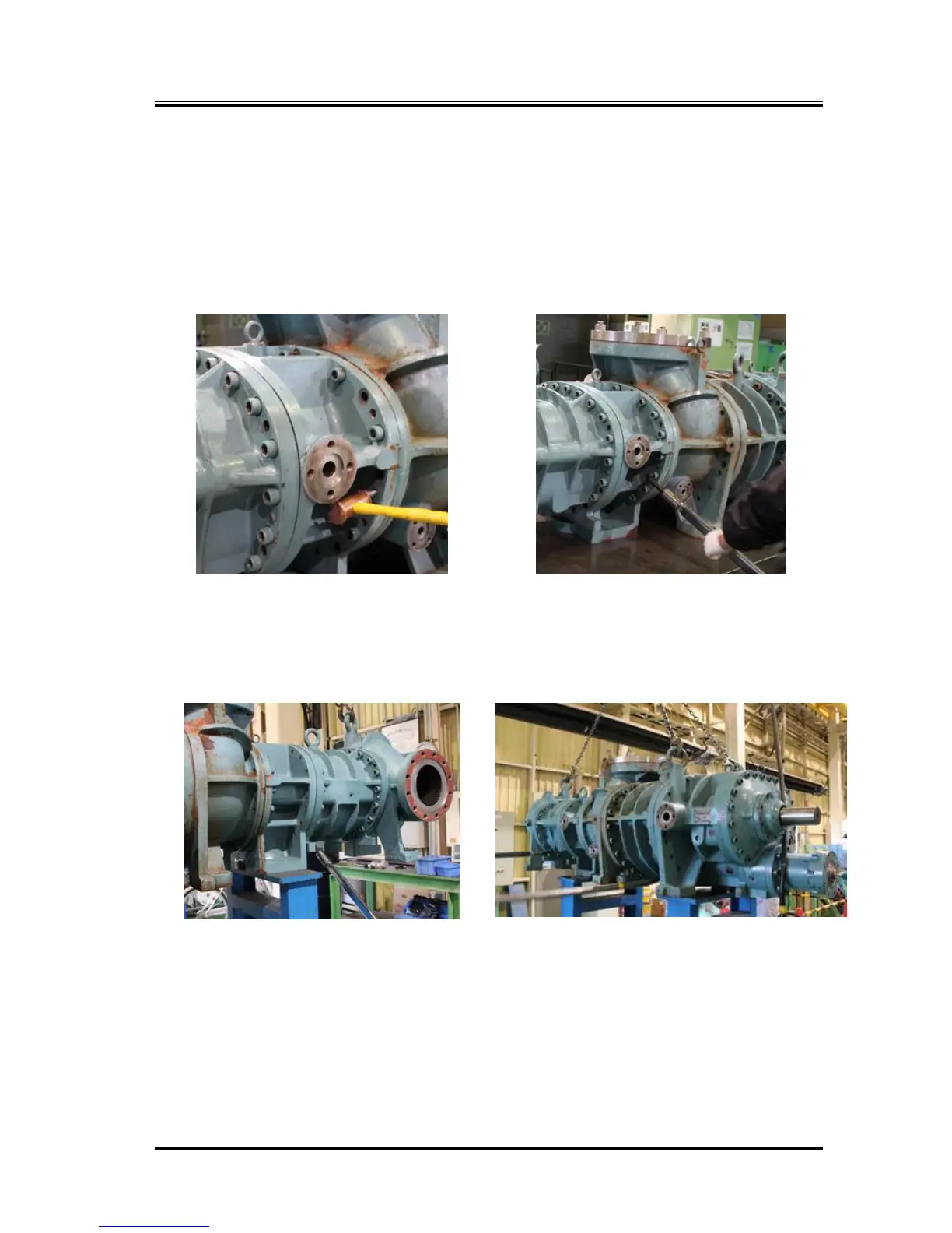
g) Once the gear coupling has been successfully engaged, push the high-stage unit onto the low-stage
unit along the rotor shaft axis. Then, insert 4 to 6 hexagon socket head cap screws [18-2] into the
bolt holes, while avoiding the bolt holes that are adjacent to the left and right alignment pins, and
temporarily fasten them evenly to eliminate the clearance between the low-stage and high-stage
flanges.
h) After the flange surfaces have contacted, slightly loosen the bolts that have been temporarily
fastened. Then, drive in the left and right alignment pins [19-2] (Photo 122).
i) Rotate the low-stage M rotor using a special tool or something to check that no abnormality is found.
j) Tighten the hexagon socket head cap screws at the specified torque of 450 N・m (Photo 123). The
lower bolts must be tightened with the compressor placed on a special stand as in the case of
disassembly (Photos 124 and 125). Do not forget to attach bottom drain plugs while the compressor
is placed on the special stand.

 Loading...