2202MYJE-MY-C8-N_2018.02.
Chapter 5 Maintenance and Inspection
Compound 2-stage Screw Compressor 3225**C 5.4 Disassembly and Inspection
5-29
5.4.10 High-stage Suction Cover and Side Bearings
If the work sequence is such that the thrust bearing block is disassembled first and then the suction
cover is removed, there is a risk that, when the suction cover is separated from the main rotor casing,
the rotor may also be pull out and dropped. As such, in the procedure described in this manual, the
suction cover is removed first, and then the thrust bearing is disassembled.
In this procedure to remove the suction cover before disassembling the thrust bearing
block, it is necessary to sufficiently loosen the lock nut that are securing the thrust
bearing while the rotor is supported by both the main and side bearings, in order not to
damage the rotor during the disassembly process.
5.4.10.1 Disassembly
a) Remove the hexagon head bolts [45-2] and the conical spring washers [46-2] that are used to fasten
the thrust bearing gland [43-2], and then remove the gland.
In case of a former model which uses a rotation stopper fitting instead of a conical spring washer,
extend the bent plate of the rotation stopper and remove it from the hexagon head blot [46-2], and
then remove the hexagon head bolt and the thrust bearing gland.
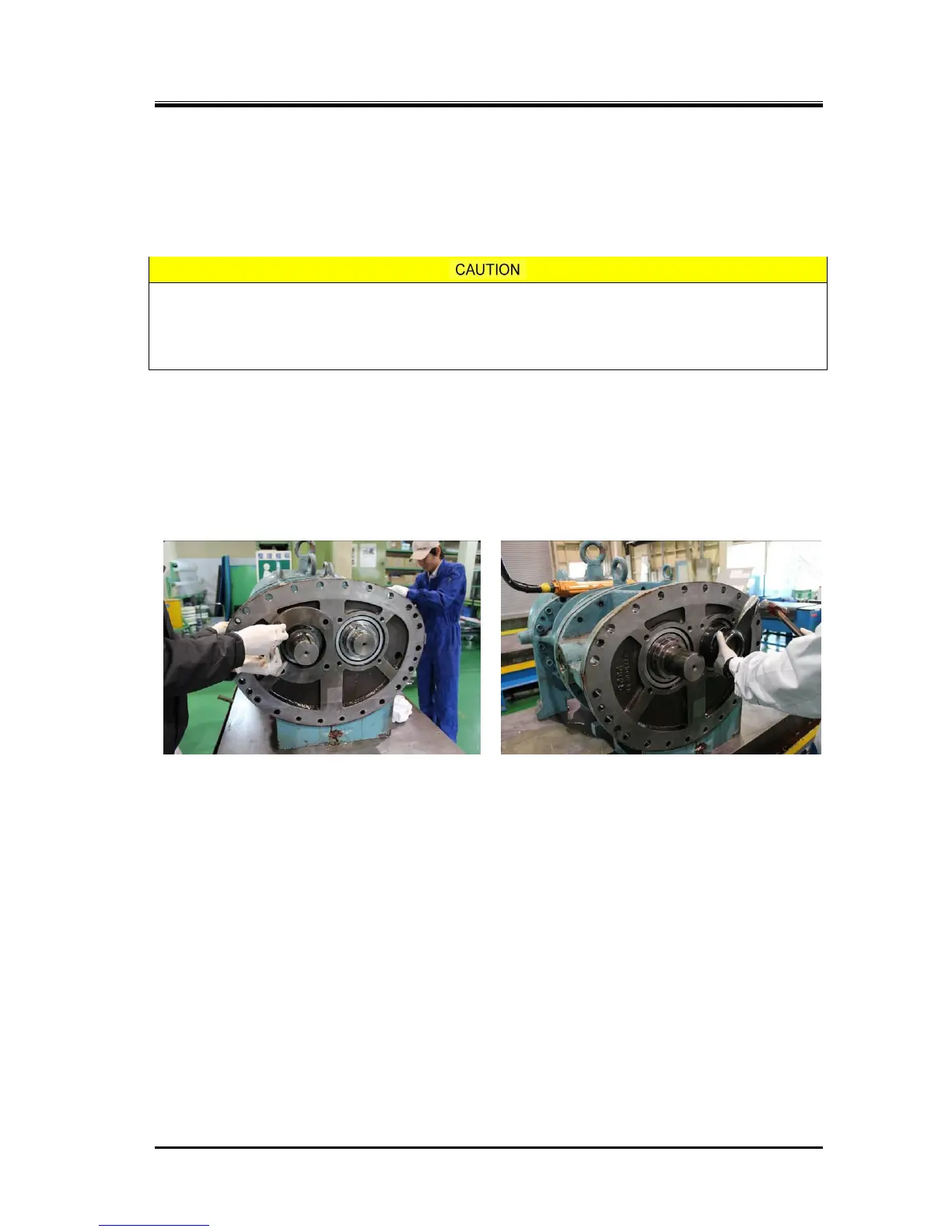
Photo 033 Removal of Hexagon Head Bolts
Photo 034 Loosening the Lock Nut
b) Unbend the rotation stopper tooth of the lock washer [40-2] holding the lock nut [39-2] which retains
the inner race of thrust bearing [38-2] on the rotor shaft and loosen the lock nut using a lock nut
wrench.
c) As the height of the high-stage main rotor casing is low, the casing is installed like a bridge to
connect between the suction cover and the bearing head. As such, the main rotor casing will be
supported only by one side (i.e., overhang) when the suction cover is removed. To avoid this, either
place squared timbers or use a lifting device to properly support the main rotor casing.
d) Loosen and remove the hexagon socket head cap screws [2-2] securing the high-stage suction
cover [5-2] to the high-stage main rotor casing [1-2].
e) As the gasket [6-2] of the suction cover is sticking to the surface of the flange, screw two hexagon
socket head cap screws [2-2] that have been removed into the screw holes in the main rotor casing
flange to evenly push the suction cover. When some gap is observed between them, use a scraper
to remove one side of the gasket from the surface.
f) When it comes to the position the alignment pins are disengaged, pull out the suction cover at once
along the rotor axis.
g) As the high-stage suction cover is installed with an O-ring [328] and O-ring gland [326-2] in the
opening for the push rod to pass through, remove them. As the four bolts fastening the O-ring gland
are small (M5), be careful not to lose them.

 Loading...