2202MYJE-MY-C8-N_2018.02.
Chapter 5 Maintenance and Inspection
Compound 2-stage Screw Compressor 3225**C 5.4 Disassembly and Inspection
5-24
5.4.5 Bearing Cover
The bearing cover [16] should be removed when the low-stage thrust bearing block is inspected or the
rotor is pulled out for inspection.
5.4.5.1 Disassembly
a) Unscrew and remove all the hexagon socket head cap screws [18-1]. The bearing cover remains
attached to the bearing head [11-1] with two alignment pins [19-1].
b) For safety, screw two stud bolts into appropriate top bolt holes.
c) There are two jacking screw holes in the opposite positions. By screwing in two left and right M8 eye
bolts evenly, the bearing cover will be separated from the bearing head. When some gap is
observed between them, use a scraper to remove one side of the gasket [17-1] from the body.
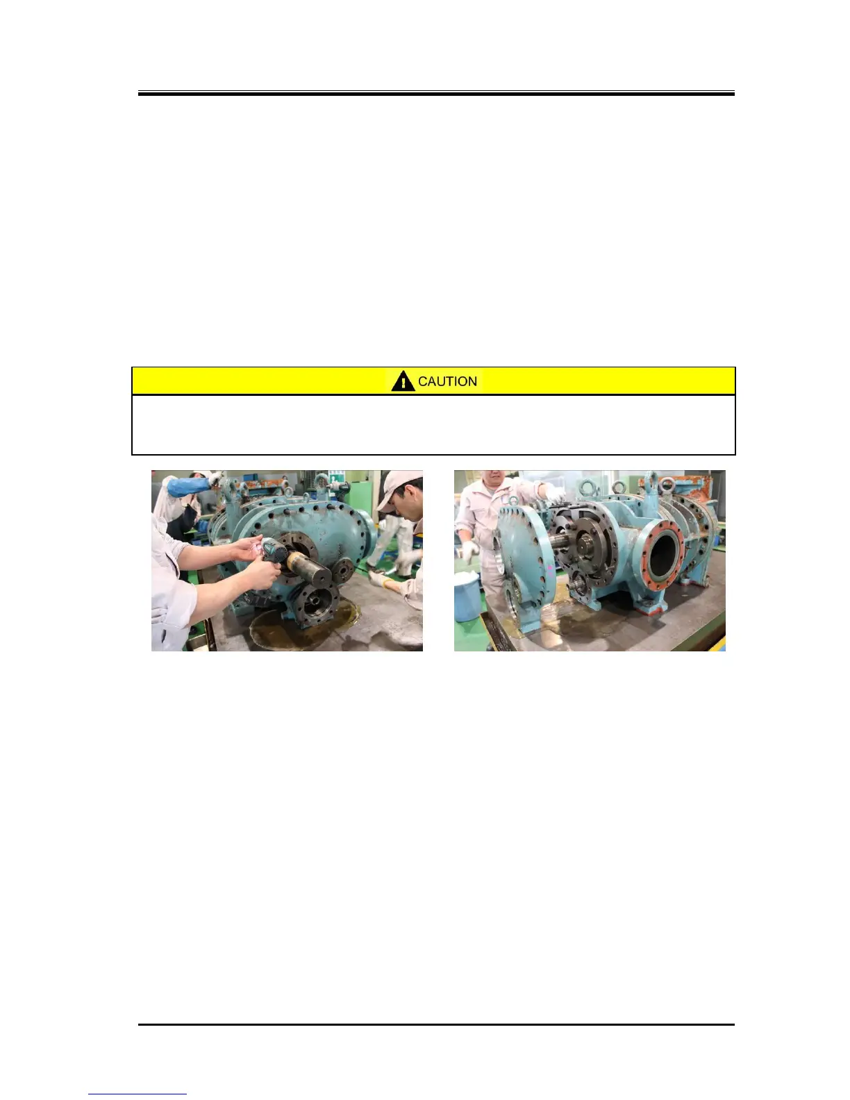
d) Further screwing in the eye bolts will disengage the bearing cover from the alignment pins.
At this point, if the bearing cover is not properly supported, it may fall or drop down
onto the rotor shaft to cause damage on it. So, be sure to protect the shaft with a
blanket or other protective covering before starting the work.

 Loading...