2202MYJE-MY-C8-N_2018.02.
Chapter 5 Maintenance and Inspection
Compound 2-stage Screw Compressor 3225**C 5.5 Reassembly
5-52
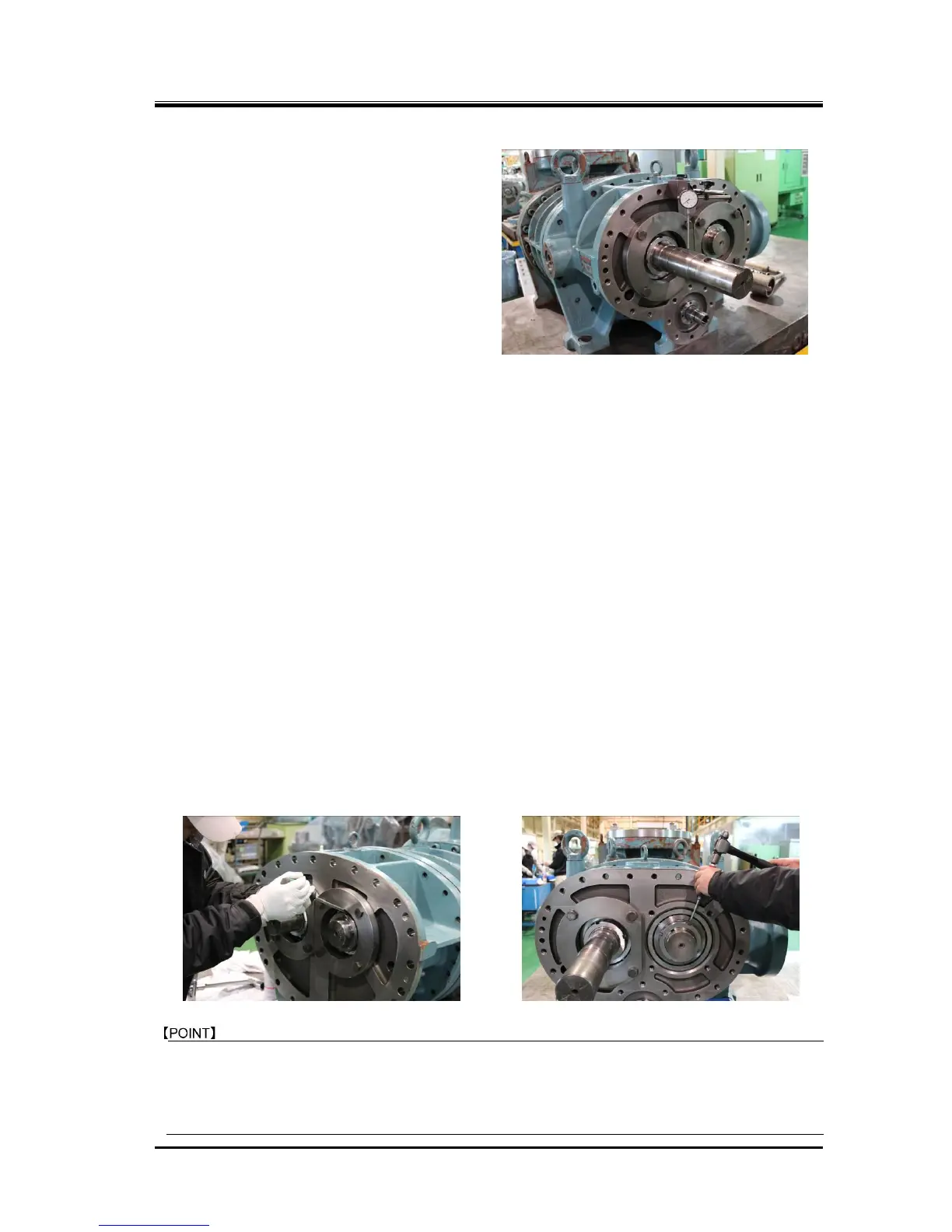
(3) Measuring the run-out of the rotor shaft
(low-stage M rotor)
If the end clearance adjustment has been
successfully completed, then measure the
run-out of the low-stage M rotor shaft
using a dial gauge at the point of the
mechanical seal attachment and turning
the shaft by hand (Photo 084).
A run-out of up to 0.03 mm is acceptable
for all models. The run-out occurs if the
thickness of the thrust alignment spacer is
not uniform or the marking on the thrust
bearing is not properly positioned. And it
occurs if fastening the lock nut performed
without changing the position of the lock nut wrench (i.e., the uneven fastening of the lock nut).
The run-out also becomes significant if any small foreign matter is present in between relevant
parts.
If the run-out exceeds the allowable value, disassemble the unit again even if the end clearance
is within the specified limits, and adjust the relative position of the alignment spacer and thrust
bearing.
This adjustment is very important as any run-out affects the function and service life of the
mechanical seal.
5.5.8.3 Tightening after Finishing the End Clearance Adjustment
a) Remove the thrust bearing glands [43-1] of the low-stage.
b) Attach the O-rings [150] to removed thrust bearing glands. Without inserting the conical spring
washers in the same manner as in the case of the end clearance measurement/alignment,
clearance, tighten the hexagon head bolts i n a diagonal sequence, a little at a time, and finally
tighten them to the specified torque.
The procedures after this are same both low-stage and high-stage.
c) Remove one of the hexagon bolts fastening the thrust bearing gland [43], insert the conical spring
washer [46], tighten the bolt at the specified torque, and repeat this procedure for all other hexagon
head bolts.
d) Bend the tooth of the lock washer to set it in the notch of the lock nut fastening the inner race of the
thrust bearing to prevent loosening (Photos 085 and 086). The these steps c) and d) may be
performed in reverse order.
Conical spring washer has been adopted instead of the plate type lock washer from October, 2001.
When using the conical spring washers for the compressors produced before this modification, the
hexagon head bolt heads may interfere with the low-stage bearing cover inner face.
In case of overhauling the compressor produced before October, 2011, do not change the lock
washer [46] to the conical spring washer.

 Loading...